Design Ownership
Requirements, architecture, schematic and PCB layout decisions managed by an experienced engineering team.

Move from product requirements to a tested electronic prototype with coordinated hardware architecture, schematic design, PCB layout, component selection, fabrication, sourcing and in-house SMT assembly.
Excel Circuit coordinates the electrical design and production stages that turn a hardware concept into buildable PCB data and an assembled, testable prototype.
Requirements, architecture, schematic and PCB layout decisions managed by an experienced engineering team.
PCB fabrication, BOM sourcing and SMT assembly planned around the released engineering data.
Inspection, testing and debugging results returned to engineering for the next design decision.
Architecture work translates product requirements into functional blocks, interfaces, power domains and critical component choices.
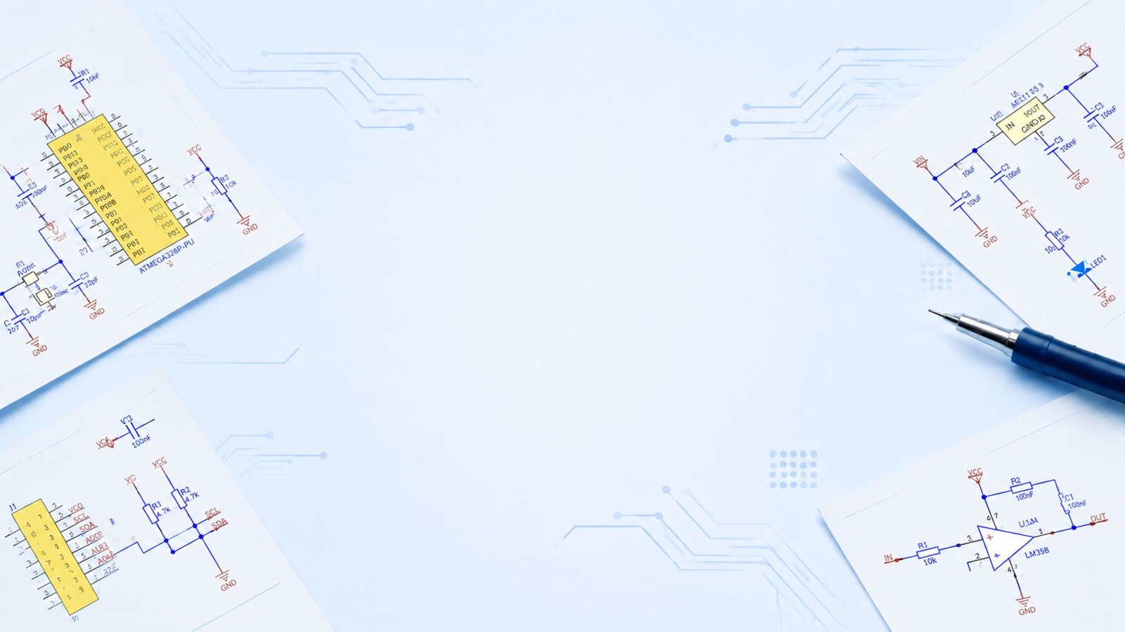
Schematic development connects the selected architecture to circuits that can be reviewed, simulated where appropriate and prepared for PCB layout.
PCB layout combines placement, routing, stackup and manufacturability controls for demanding electronic systems.
Controlled impedance, differential routing, return paths, grounding and material coordination.
Microvia planning, BGA fan-out and dense multilayer routing.
Current paths, copper distribution, thermal vias and isolation requirements.
Functional partitioning, sensitive paths, grounding and noise control.
Memory buses, clocks, high-speed interfaces and power integrity.
Fabrication and assembly checks before manufacturing data release.
Component decisions are reviewed against electrical requirements, package constraints, lifecycle status and sourcing conditions.
Electrical ratings, performance, interfaces and operating conditions.
Footprint, assembly process, thermal behavior and layout implications.
Lead time, lifecycle status and practical alternative parts.
Manufacturer details, approved substitutions and sourcing notes.
Prototype planning connects design maturity, build quantity, component availability and the tests needed to make the next engineering decision.
Define quantities, assembly variants, critical interfaces and acceptance checks.
Review Gerber, drill, stackup, BOM, placement and assembly documentation.
Capture build findings and prioritize changes for the next revision or pilot run.
PCB manufacturing services and component sourcing are aligned to the released design package without implying that every bare-board process is performed in a single owned facility.
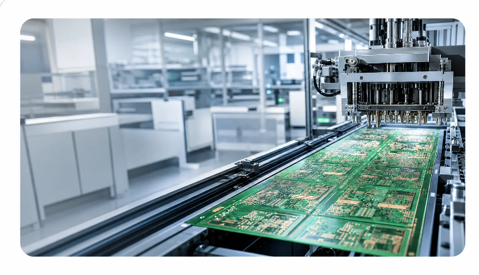

In-house SMT capability enables fast communication between production and engineering during stencil review, placement, reflow and inspection.
Testing scope is defined around the project so assembly quality, power-up behavior and critical interfaces can be checked and documented.
Check component presence, orientation, solder joints and workmanship.
Continuity, shorts, power rails and selected electrical measurements.
Controlled power-up and review of critical hardware interfaces.
Document findings and identify layout, component or assembly changes.
Engineering and prototype support can be adapted to the electrical, environmental and production requirements of each application.
Controllers, motion systems, I/O platforms and measurement equipment.
Control, sensing, power management and vehicle interface electronics.
Board-level engineering with attention to reliability and controlled documentation.
High-speed digital, RF, networking and connected embedded platforms.
A staged design-to-manufacturing workflow makes technical decisions, released data and prototype feedback visible throughout the project.
Functions, interfaces and constraints.
System blocks and component strategy.
Detailed electrical design and review.
Stackup, placement, routing and DFM.
PCB fabrication, sourcing and SMT.
Inspection, power-up and interfaces.
Document results and plan revision.
Anonymized examples illustrating design, production and validation decisions.
Control requirements, circuit architecture, schematic and PCB layout decisions coordinated through fabrication, assembly and prototype verification.
Protection, thermal and mixed-signal requirements coordinated from component selection through assembly and prototype validation.
Analog and digital architecture, schematic and layout engineering, PCBA build support and functional signal testing.
Share the product functions, interfaces, power requirements, operating environment, expected size, target quantities and any existing block diagrams, schematics or component preferences.
Yes. The engineering scope can include hardware architecture, schematic capture, PCB layout and design-for-manufacturing review.
Yes. Prototype support can include PCB fabrication coordination, component sourcing, in-house SMT assembly, inspection and agreed testing.
These are not presented as standalone services on this page. Embedded hardware interfaces and board-level mechanical constraints can be coordinated within the electrical engineering scope; any additional scope should be confirmed for the specific project.
Yes. After prototype validation, the team can review design changes, sourcing conditions, manufacturing documentation and the controls required for pilot or repeat production.