
Purchasing FAQ
Practical answers about files, schedule, engineering support, production coordination and confidentiality.
To start RF PCB Design, send your system requirements, block diagram, schematic or netlist if available, component datasheets, mechanical constraints, connector locations, stackup preferences, and any impedance, power, thermal, EMC or test requirements. Existing Gerber or ODB++ files can also help us understand a previous revision.
Lead time depends on design maturity, complexity, quantity, material or component availability, testing scope, and how quickly engineering questions are resolved. We confirm the schedule after reviewing your files; urgent prototype or quick-turn options can be discussed where the required process and materials permit.
We can review common production outputs such as Gerber and ODB++, as well as native EDA data when agreed during the file review. Because library versions, third-party models and tool releases vary, tell us the software and version used before transfer so we can confirm the working format or recommend a neutral export.
Yes. We can work from an existing design, production package or previous revision. We first check completeness, revision control and the requested scope, then identify any missing data, manufacturability risks or changes that need your approval before work begins.
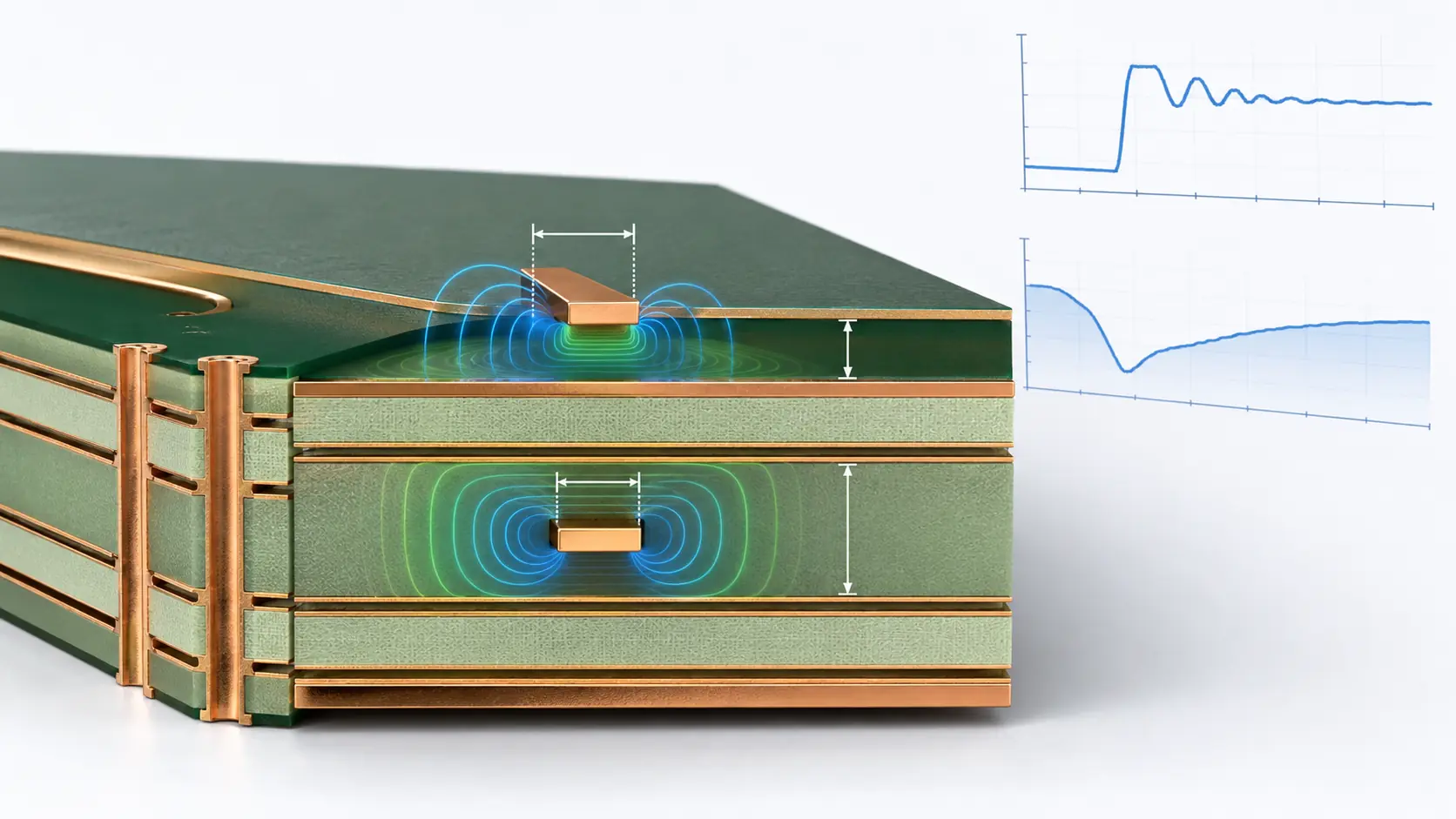
Yes. SI/PI review or simulation can be included when the design contains high-speed interfaces, sensitive analog sections or demanding power rails. Scope depends on available stackup data, IBIS/SPICE models and measurable acceptance targets, so it is quoted separately when needed.
Yes. Excel Circuit can coordinate engineering review, PCB fabrication, component sourcing, assembly, inspection and testing under one project. You may also order only the engineering stage and release the approved production package to another manufacturer.
Project files are limited to personnel and qualified partners who need them for quotation and delivery. Excel Circuit uses reasonable technical and organizational safeguards, does not publish customer designs without permission, and can work under a mutually agreed NDA. Your signed NDA or project agreement controls where it provides specific protections.
Final scope, price and lead time are confirmed after engineering review of your current files and requirements.