Contents
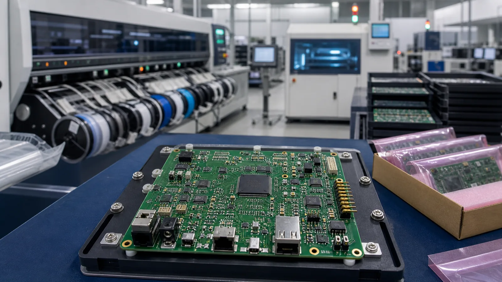
Turnkey PCB assembly is a coordinated production workflow in which one supplier manages manufacturing-data review, component sourcing, PCB fabrication coordination, SMT and through-hole assembly, inspection, project-specific testing, final quality review, packaging, and shipment. After a customer submits Gerber or ODB++ data, a BOM, placement data, quantities, and test requirements, each approved input becomes part of a controlled path from quotation through finished PCBA delivery.
The value of the turnkey model is coordination. PCB data, component availability, assembly requirements, and test expectations must describe the same product revision before material is purchased or production begins. Excel Circuit combines qualified PCB manufacturing resources, component sourcing, and in-house SMT assembly to support prototype-to-production projects without describing PCB fabrication as an in-house operation.
Turnkey PCB Assembly Process at a Glance
| Stage | What happens | Customer input or output |
|---|---|---|
| 1. RFQ and file review | The supplier checks whether the production package is complete and suitable for quotation. | Gerber or ODB++, drill data, BOM, placement data, drawings, quantities, and requirements |
| 2. Engineering / DFM review | Board, assembly, and placement data are compared for manufacturability and consistency. | Clarifications, risk notes, and approved revisions |
| 3. BOM review | Part numbers, packages, quantities, lifecycle, availability, and alternates are evaluated. | Approved BOM and substitution decisions |
| 4. Component sourcing | Parts are procured with attention to availability, packaging, traceability, MOQ, and lead time. | Resolved shortages and approved alternates |
| 5. PCB fabrication coordination | Qualified PCB manufacturing resources produce the bare boards to the approved specification. | Released PCB data, stackup, material, finish, and impedance requirements |
| 6. Incoming inspection | Bare boards and components are checked before assembly. | Accepted materials or documented discrepancies |
| 7. Solder paste printing | A stencil deposits solder paste on the required surface-mount pads. | Printed boards ready for placement |
| 8. SMT placement | Programmed equipment places surface-mount components from prepared feeders. | Populated boards before soldering |
| 9. Reflow soldering | A controlled thermal profile forms the surface-mount solder joints. | Reflowed SMT assemblies |
| 10. THT / manual assembly | Through-hole and odd-form parts are installed using the appropriate soldering method. | Mechanically complete assemblies |
| 11. Inspection | Visual inspection, AOI, and X-ray where appropriate evaluate assembly workmanship. | Inspection records and disposition of identified defects |
| 12. Electrical / functional testing | The agreed test plan checks electrical behavior, programmed functions, or product operation. | Test results and accepted assemblies |
| 13. Final quality review | Revision, quantity, assembly completeness, test status, and packaging readiness are confirmed. | Released finished lot |
| 14. Packaging | Assemblies are protected, labeled, and prepared for the specified shipping conditions. | Packed PCBA lot and shipment documents |
| 15. Shipment | The completed order leaves with the agreed identification and logistics documents. | Tracking or freight information |
The stages are connected rather than isolated. A BOM availability issue can change an approved alternate; the alternate can change a footprint or placement requirement; that change must be resolved before programming placement equipment or releasing production.
1. RFQ and Production File Review
RFQ and production-file review establishes what will be built, how many assemblies are required, and which requirements control the quotation. A typical starting package includes Gerber or ODB++ data, NC drill files, a BOM, pick-and-place or centroid data, an assembly drawing, board and assembly quantities, and any applicable test or programming instructions.
File names alone do not establish revision control. The supplier must confirm that fabrication data, assembly drawings, placement coordinates, and the BOM belong to the same released design. Customers who need a detailed submission list can use the complete PCB production package checklist rather than treating this process overview as a file-format specification.
Quotation assumptions should also identify approved alternates, consigned materials, target timing, special handling, packaging expectations, and the scope of testing. Clear inputs reduce later commercial changes, but a quote is not yet a production release; unresolved technical questions must proceed through engineering review.
2. Engineering Review and DFM / DFA Check
Engineering review checks whether the released product data can be fabricated, assembled, inspected, and tested as intended. A combined DFM, DFA and DFT review connects those decisions across production stages. The review compares board dimensions and layers, footprints and polarity markings, component clearances, panel considerations, placement information, BOM entries, and known process risks. DFM addresses fabrication constraints, while DFA focuses on assembly access, orientation, spacing, and process suitability.
A useful review produces specific questions or decisions rather than a generic approval label. For example, a footprint mismatch requires a data correction or documented component decision; a polarity conflict requires confirmation from the design owner; and a panel constraint may require coordination with the selected PCB resource. The PCB design for manufacturability guidelines cover design-level checks in greater depth.
Procurement and production should use the same approved revision that emerged from this review. Late design changes can invalidate quotations, component reservations, stencils, machine programs, test fixtures, or already fabricated boards.
3. BOM Review
BOM review converts a component list into an actionable sourcing and assembly record. The review checks manufacturer part numbers, required quantities, package descriptions, lifecycle status, availability, approved alternates, and special sourcing or handling instructions. Reference designators and placement quantities should agree with the assembly data.
Descriptions such as “10 k resistor” are not sufficient when package, tolerance, power rating, temperature coefficient, or qualification affects the design. An approved manufacturer part number creates a more precise sourcing target. If substitution is allowed, the BOM should state who may approve an alternate and which electrical, mechanical, regulatory, or lifecycle attributes must remain equivalent.
The PCB assembly BOM guide explains how to prepare the component list. In the turnkey PCBA process, the important output is an approved BOM whose availability decisions are synchronized with the production revision.
4. Component Sourcing
Component sourcing turns the approved BOM into a verified material plan for the build. Supplier selection, current stock, MOQ, packaging format, lead time, traceability information, and incoming checks can affect when a complete kit is available. Long-lead or allocation-sensitive parts often determine the schedule more than the assembly operation itself.
Approved alternates can reduce supply risk, but an alternate is not merely a similar description. Package dimensions, pinout, electrical limits, firmware interaction, thermal behavior, and lifecycle requirements may require customer or engineering approval. Formal obsolete component management connects lifecycle status, availability, and approved alternate decisions. The sourcing team should document the accepted part before it enters the assembly kit.
Excel Circuit can coordinate electronic component sourcing and BOM services as part of a turnkey build. This coordination does not imply guaranteed availability or identical inspection rules for every project; sourcing controls depend on component risk and agreed requirements.
5. PCB Fabrication Coordination
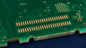
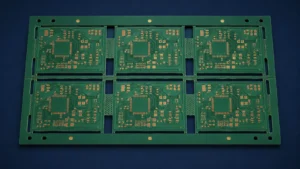
PCB fabrication coordination releases the approved bare-board specification to qualified PCB manufacturing resources and keeps it aligned with assembly needs. The release may define material system, layer stackup, copper weight, surface finish, controlled impedance, via structures, HDI requirements, panelization, and acceptance documentation.
The selected resource must match the technical requirements and intended volume. A high-layer-count impedance-controlled board, a simple two-layer prototype, and an HDI design do not require the same fabrication route. Manufacturing questions that change geometry or materials should return through controlled approval rather than being resolved informally.
PCB fabrication affects the assembly schedule because bare boards must be completed and accepted before solder paste printing. Special materials, complex stackups, sequential lamination, or nonstandard finishes may add lead time. These variables are among the factors explained in the PCB assembly cost breakdown, but this article keeps its focus on workflow rather than price calculation.
6. Incoming Material Inspection
Incoming inspection confirms that bare boards and components correspond to the released build before they enter assembly. Checks can include component identity, quantity, packaging condition, visible damage, documentation, PCB condition, and moisture-sensitive handling information where relevant.
The appropriate inspection depth depends on project requirements, material risk, supplier records, and applicable quality controls. Not every component or PCB lot requires the same protocol. Discrepancies should be segregated and resolved before the affected material is loaded into production. Review medical-electronics PCB assembly requirements when a program needs stricter traceability, inspection, and reliability controls.
Incoming acceptance creates the boundary between sourcing and assembly. A physically complete kit is not production-ready if a part identity, package, revision, or moisture-handling question remains open.
SMT Assembly Process
7. Solder Paste Printing
Solder paste printing deposits a controlled volume of solder paste onto surface-mount pads through a stencil. Stencil aperture design, board support, paste condition, alignment, and printing parameters influence deposit consistency. The printed deposits must support the component and pad geometries on the assembly.
Printing is an early process-control point because insufficient, excessive, bridged, or misaligned paste can propagate into reflow defects. The process setup should reflect board design, component mix, stencil design, and solder-paste requirements rather than rely on one universal setting.
8. SMT Placement
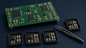
SMT placement uses programmed pick-and-place equipment to position surface-mount components on the printed solder paste. Preparation includes machine programming, feeder setup, package recognition, orientation checks, fiducial alignment, and confirmation that reference designators correspond to the released placement file.
Fine-pitch devices, BGAs, QFNs, small passives, and densely populated boards require suitable placement setup and process control. Package type and board density influence assembly complexity, but placement speed or equipment capability should not be inferred without project and line data. Excel Circuit uses in-house SMT assembly for this stage of supported PCBA projects.
Customers preparing coordinate data can consult the SMT pick-and-place file guide. The turnkey workflow uses that file as a controlled machine-programming input; it does not replace drawings, BOM data, or orientation confirmation.
9. Reflow Soldering
Reflow soldering applies a controlled thermal cycle that activates the solder paste and forms surface-mount solder joints. The thermal profile must suit the solder material, board construction, component population, thermal mass, and relevant component limitations.
A profile is a process setting, not a generic temperature promise. Dense copper areas, large packages, small passives, and temperature-sensitive components can respond differently on the same board. The PCBA reflow soldering guide explains profile parameters and defect prevention without expanding those details here.
10. Through-Hole and Manual Assembly
Through-hole and manual assembly installs components that are not completed by the primary SMT sequence. Connectors, transformers, large mechanical parts, switches, cables, and odd-form devices may require additional insertion, fastening, soldering, or mechanical work.
The applicable soldering method can include wave soldering, selective soldering, or hand soldering. Component mix, board design, thermal demand, keepouts, volume, and workmanship requirements determine the suitable route; turnkey PCBA does not mean that every through-hole component is soldered by hand.
Manual operations may also include hardware installation, wire preparation, or other project-defined work. Drawings and work instructions should identify orientation, torque, adhesives, special materials, or mechanical acceptance criteria where those details matter.
11. Inspection After Assembly
Post-assembly inspection evaluates workmanship and process evidence, while testing evaluates electrical or functional behavior. Visual inspection can identify assembly completeness and visible soldering issues. AOI can compare visible component placement and solder-joint features against programmed criteria. X-ray may be used when package construction and quality requirements justify examination of hidden joints.
BGA and QFN terminations cannot be fully evaluated from the top surface, but that does not mean every BGA on every project receives the same X-ray plan. Package risk, process validation, customer requirements, and inspection strategy determine the method. The BGA assembly and inspection guide covers hidden-joint considerations in more detail.
Inspection results can trigger review, rework, or process correction before the lot advances. A visually acceptable board can still fail electrically, which is why inspection and testing remain separate stages.
12. Electrical and Functional Testing
Electrical and functional testing checks whether the assembled board meets the agreed acceptance plan. Depending on the product and scope, the plan may include basic electrical checks, in-circuit testing, programming, functional testing, or a customer-defined fixture and procedure.
Test coverage is project-dependent. A supplier needs test limits, firmware, fixture responsibilities, connector access, power requirements, expected outputs, and failure-disposition instructions early enough to plan the build. Missing test requirements discovered after assembly can delay fixture preparation and product acceptance.
Excel Circuit provides PCB testing support according to the agreed project scope. This workflow overview identifies where testing belongs; use the PCB assembly testing methods comparison for AOI, X-ray, ICT, and functional test selection.
13. Final Quality Review
Final quality review confirms that the completed lot matches the released order and is ready for packaging. The review can cover assembly completeness, visible condition, accepted revision, quantity, inspection status, test-result disposition, required labels, and outstanding documentation.
The final review should use the requirements agreed for the project rather than an invented universal checklist. Any concession, rework record, quantity variance, or unresolved result that affects acceptance should be settled before shipment release.
14. Packaging and Shipment
Packaging and shipment protect accepted assemblies and preserve their identification through delivery. Packaging may include ESD-aware materials, moisture protection where applicable, physical separation, product labels, lot or revision identification, and project-specific packing instructions.
Shipment documents and labeling should let the recipient identify what arrived and relate it to the order. Transport mode, destination, assembly sensitivity, quantity, and customer requirements influence the packaging plan; no single packing method fits every PCBA.
Turnkey vs Consigned PCB Assembly
Turnkey assembly assigns sourcing and production coordination to the PCBA supplier, while consigned assembly uses materials supplied partly or entirely by the customer. Neither model is always better; the right choice depends on supply agreements, component ownership, schedule, traceability needs, and internal procurement resources.
| Item | Turnkey | Consigned |
|---|---|---|
| Component procurement | Supplier coordinates procurement for the approved BOM. | Customer supplies some or all components. |
| PCB sourcing | Supplier coordinates bare-board fabrication. | Customer may provide completed bare boards. |
| Supplier coordination | Centralized through the assembly supplier. | Shared with or retained by the customer. |
| Customer workload | Lower day-to-day sourcing coordination after approvals. | Higher responsibility for kit completeness and delivery. |
| Supply risk management | Availability and alternates are coordinated within the build. | Customer controls selected sources and inventory decisions. |
| Lead-time coordination | PCB, components, and assembly are planned together. | Assembly timing depends on arrival of the consigned kit. |
A hybrid model is also possible when the customer consigns controlled, programmed, scarce, or existing-stock parts while the supplier sources the balance. Responsibilities should be defined at quotation so ownership, shortages, attrition allowances, and unused material disposition are clear.
Information Required From the Customer
A complete turnkey PCBA review needs enough information to define the board, component population, quantity, acceptance plan, and delivery objective. The starting checklist normally includes:
- Gerber or ODB++ fabrication data
- NC drill data
- BOM with manufacturer part numbers
- Pick-and-place or centroid data
- Assembly drawing and polarity information
- Bare PCB quantity and assembly quantity
- Approved alternates and approval authority
- Testing requirements and acceptance limits
- Programming files and instructions where applicable
- Target schedule and delivery destination
- Special labeling or packaging requirements
The exact requirement varies by project. Use the production package checklist to review the detailed file set before requesting quotation.
Common Causes of Turnkey PCBA Delays
Turnkey PCBA delays most often begin with unresolved data, supply, revision, or test dependencies rather than with one assembly operation. Customers and suppliers can reduce avoidable waiting by identifying the controlling dependency before material release.
- Incomplete BOM: Missing MPNs, quantities, packages, or reference designators prevent reliable sourcing and kit reconciliation.
- Unavailable parts: Long lead times, allocation, MOQ, or obsolete components can hold the full kit.
- Unclear alternates: A substitution cannot proceed when equivalence criteria or approval authority is undefined.
- Mismatched revisions: Gerber, BOM, placement, and drawing files from different revisions create unsafe production choices.
- Missing placement data: Incomplete coordinates, rotations, side information, or fiducials delay machine programming.
- Unclear polarity: Conflicts between footprints, drawings, datasheets, and markings require design-owner confirmation.
- Late design changes: A change after purchasing or fabrication can affect parts, boards, stencils, programs, and fixtures.
- Incomplete test requirements: Late limits, firmware, fixtures, or procedures can leave finished assemblies without an acceptance path.
- Special PCB materials or structures: Nonstandard laminates, HDI, sequential lamination, or special finishes may control bare-board lead time.
A practical prevention method is to maintain one approved release package, one decision log for open questions, and named approval responsibility for substitutions or manufacturing changes. This creates a traceable path without turning the process into a supplier disclaimer.
Prototype vs Production Turnkey PCBA
Prototype and production turnkey builds use the same basic stages but place different emphasis on change control, setup, sourcing, and repeatability. Prototype builds usually involve smaller quantities, more engineering interaction, evolving files, and a higher setup burden per assembly. The goal is often to learn quickly while preserving enough control to identify what was built.
Production builds require a stable revision, repeatable process settings, supply planning, controlled test coverage, and consistent release documentation. Changes still occur, but they should pass through formal approval because larger material commitments and repeated builds increase the impact of an uncontrolled revision.
A successful prototype is not automatically production-ready. Before scaling, the team should resolve prototype substitutions, update files to the as-built revision, confirm test coverage, review supply continuity, and define which process records or acceptance criteria must remain stable.
Frequently Asked Questions
What files are needed for turnkey PCB assembly?
Turnkey PCB assembly normally requires Gerber or ODB++ data, NC drill files, a BOM, pick-and-place data, an assembly drawing, quantities, and applicable testing or programming requirements. Complex projects may require additional fabrication, mechanical, firmware, or acceptance information.
What is included in turnkey PCB assembly?
Turnkey PCB assembly can include file and engineering review, component sourcing, bare-PCB fabrication coordination, SMT and through-hole assembly, inspection, project-specific testing, final review, packaging, and shipment. The exact scope must be defined in the quotation.
What is the difference between turnkey and consigned PCB assembly?
In turnkey assembly, the supplier coordinates PCB and component sourcing as part of the build. In consigned assembly, the customer supplies some or all production materials and remains responsible for delivering a complete, approved kit.
Does turnkey PCB assembly include component sourcing?
Yes, component sourcing is commonly part of turnkey PCB assembly. The supplier reviews the BOM, coordinates availability and packaging, and submits alternates for approval when required; availability is not guaranteed for every specified part.
How does testing fit into the turnkey PCBA process?
Testing follows assembly and inspection and checks the electrical or functional requirements agreed for the project. Test coverage, fixtures, firmware, limits, and acceptance criteria are product-specific and should be defined before production.
Request a Turnkey PCBA Production Review
Send your Gerber or ODB++ files, BOM, placement data, assembly quantity, and test requirements for a coordinated turnkey PCBA review. Excel Circuit can review the production package, coordinate qualified PCB manufacturing resources and component sourcing, complete in-house SMT assembly, and plan inspection and testing support around the approved project scope.
Review turnkey PCBA service capabilities or request a turnkey PCBA review.