First article inspection for PCB assembly verifies that an initial assembled unit matches the released design data, BOM, placement requirements, workmanship expectations, polarity, solder-joint requirements and programming/test requirements before a larger batch proceeds. Its purpose is to catch systematic errors before they are repeated across production quantity. A board that looks correct is not necessarily ready for release: the first-build review must connect physical observations with the correct revisions, test evidence and an approval decision.
Use the following checklist to define the review scope with engineering and manufacturing before assembly starts. The applicable checks and records depend on the product, customer quality system and agreed production requirements.
| Inspection area | What to verify | Typical risk |
|---|---|---|
| PCB revision | Board identity against released fabrication and assembly data | Building the correct BOM onto an obsolete board |
| BOM | MPN, value, package, quantity and approved alternates | Wrong component or unapproved substitution |
| Placement | Reference designator, location and rotation | Systematic placement-program error |
| Polarity | Diodes, ICs, polarized capacitors and connectors | Functional failure or damage during power-up |
| Solder joints | Wetting, alignment, bridges, opens and insufficient solder | Repeated assembly defect |
| BGA/QFN | Hidden joints and exposed-pad condition where applicable | A defect missed by surface inspection |
| Programming | Released firmware, configuration and version evidence | Correct hardware running the wrong image |
| Functional test | Defined behavior under specified test conditions | Undetected performance or interface fault |
| Documentation | Revision, result, deviation and approval records | An unrepeatable or untraceable release decision |
On a narrow screen, scroll the table horizontally. Keyboard users can focus the table region and use the arrow keys.
What Is PCBA First Article Inspection?
PCBA first article inspection is a first-build verification gate. It checks whether the released instructions have produced the intended assembly and whether the evidence supports continuing the build. It can reveal a mirrored placement file, an incorrect feeder assignment, an ambiguous polarity mark or a test requirement that was never transferred into production instructions.
Different industries use “FAI” differently. The aerospace 9102 first article inspection framework is a separate, formal context; this practical PCBA checklist does not establish AS9102 compliance. Agree the deliverable, sampling scope and approval authority for the actual job. One acceptable first unit also does not establish long-term process capability or prove that every later unit will pass.
Verify PCB Revision and Manufacturing Data
Start with the build identity. Reconcile the PCB marking and fabrication release with the assembly drawing, BOM and placement-data revisions. These documents may have different revision labels, so the requirement is a controlled, compatible release set rather than identical letters on every file. Check whether an engineering change order applies to this lot and whether it was incorporated or explicitly deferred.
Resolve conflicting drawings before inspection becomes a debate over which file is current. Record the approved baseline and remove superseded instructions from the production work package. The PCB manufacturing and production file checklist explains the supporting input package. First article inspection then verifies the physical assembly against that package; it cannot repair an undefined release by observation alone.
Check the BOM Against the Installed Components
Verify manufacturer part number, value, package and installed quantity against reference designators. Review approved alternates and substitutions as controlled decisions, including any changed orientation, ratings or programming implications. A visually similar package is not evidence that a component is electrically interchangeable.
Include DNI/DNP locations: an intentionally empty position should remain empty, and a missing required component should not be mistaken for an option. Where markings are incomplete or too small to identify a part reliably, reconcile assembly records, reel or package labels and the material assignment. Inspection should identify uncertainty rather than turn an unreadable marking into an assumed pass. Confirm option variants explicitly, especially when several BOM configurations share the same bare PCB.
Verify Placement, Polarity and Orientation
Check reference designators, XY position, board side and rotation against the assembly drawing and component documentation. Placement coordinates describe a machine instruction; they do not by themselves demonstrate that the chosen origin, orientation convention and package library were correct. Inspect asymmetric parts and connector keying as physical relationships to the board.
Review diode polarity, IC pin-one orientation, polarized capacitors and connectors before power is applied. Resolve differences between silkscreen symbols and manufacturer markings through the released design authority. Include mechanically similar connectors that can be fitted in the wrong position. A consistently rotated package across the first board is a reason to investigate the program or library before assembling the remaining quantity.
Inspect Solder Joints and Component Alignment
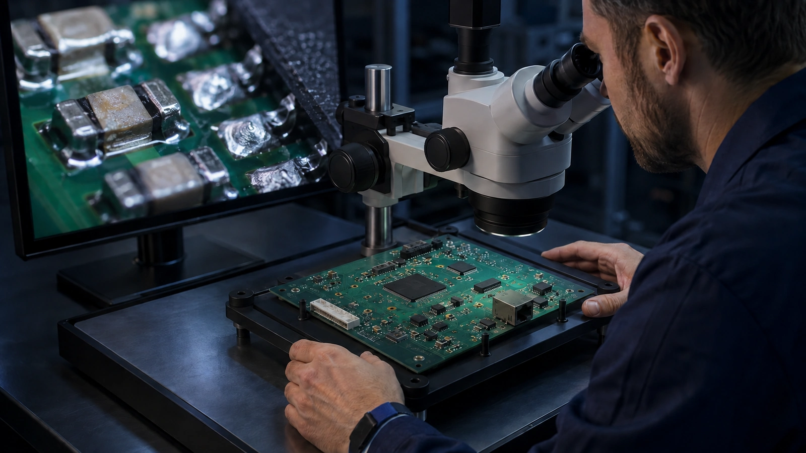
Use the agreed workmanship requirements to review wetting, bridges, opens, insufficient solder, tombstoning and alignment. Record the affected reference and joint rather than writing only “solder issue.” The inspection result should say what was observed, which requirement applies and whether the condition is accepted, rejected or awaiting disposition.
A first article is a release check, not a substitute for detailed defect diagnosis. If a recurring bridge or lifted chip end is found, route it to the appropriate process investigation and confirm the correction on subsequent evidence. Avoid judging solder quality only by a shiny appearance; appearance depends on material and process, and hidden interfaces may remain unverified.
Review BGA and QFN Hidden Joints
BGA balls and QFN exposed pads cannot be fully assessed from a top-side visual check. Define which hidden features require X-Ray or another suitable inspection method, what images must be retained and who will interpret them. Record package reference designators so an image can be tied to a specific assembly and location.
For ball-joint void observations, use the distinction between image area, location and applicable acceptance requirements in BGA voiding evaluation and prevention. A QFN center pad has a different geometry and thermal role; the QFN thermal-pad, via and stencil review addresses those assembly decisions. Do not transfer a void criterion between these structures without establishing its applicability.
Understand What AOI and X-Ray Can Prove
AOI can support checks of visible placement and joint features within the equipment’s access and inspection program. It does not see every hidden connection or verify all component identities. X-Ray can reveal internal solder geometry and certain hidden defects, but interpretation depends on resolution, angle, overlap and the inspection method.
Neither an AOI pass nor an acceptable X-Ray image proves electrical function. Confirm that inspection programs match the current assembly variant and that coverage gaps are addressed in the release plan. Use the comparison of PCB assembly inspection and testing methods when deciding how optical inspection, X-Ray and electrical tests complement each other.
Verify Programming and Configuration
Where programming is required, identify the released firmware file, version, target device and relevant configuration. Establish how successful programming will be confirmed: this may involve a programmer’s verification result, a readable version identifier or an agreed checksum comparison. The evidence must relate to the intended file, not merely show that a programming operation completed.
Check option settings, boot configuration and serialization where applicable. Unique identifiers need the agreed assignment and recording controls; prototypes without such requirements do not need an invented serialization workflow. Treat an unknown firmware version as an unresolved release condition even if basic power-up appears normal. These are review considerations, not a claim that every Excel Circuit job uses the same programming system.
Run Defined Electrical and Functional Tests
Use an approved procedure with stated conditions and acceptance criteria. Before power-up, complete the required pre-power checks and resolve polarity concerns. The procedure should define the supply setup, expected current behavior, interfaces to exercise and outputs or functions to verify. Engineering must provide meaningful limits; manufacturing should not infer them from a unit that happens to operate.
Record results against the correct hardware and firmware configuration. A board may pass a limited interface check while an untested channel remains defective. Document excluded functions and any customer-approved test limitations. If no functional procedure exists, report that gap and agree a disposition rather than labeling a visual inspection as a functional pass.
Check Mechanical Fit and Assembly Access
Verify connector location, component height, mounting-hole access and possible mechanical interference against the released mechanical requirements. Consider mating parts, fasteners and enclosure fit where these are part of the job. A correct electrical connector can still prevent installation if its height, keying or orientation is wrong.
Use an applicable mechanical drawing or a controlled fixture or sample where agreed. Identify whether fit was physically checked or only reviewed against dimensions. A missing enclosure does not justify an unqualified fit approval; it creates a specific limitation that the responsible team must resolve or accept.
Keep Documentation and Traceability Proportionate
A useful first article record connects the inspected unit, released revisions, inspection/test results, nonconformances and disposition. Add serial or lot information, component traceability and retained images to the extent required by the product and contract. Not every engineering prototype needs full production traceability, but every approval should be understandable to the next person responsible for the build.
Record approved deviations with their scope, authority and applicability. An email accepting a single prototype condition should not silently become a permanent production instruction. Keep the first article evidence associated with the build release so later changes can be assessed against a known baseline.
What Happens If the First Article Fails?
- Contain the issue. Hold affected work and identify any units already assembled under the same conditions.
- Describe the nonconformance. Record the location, observed result, expected requirement and available images or measurements.
- Separate design, process and material causes. Check whether the released instruction was wrong, the process departed from it or the supplied material was unsuitable.
- Control the correction. Obtain approval for document changes, material decisions or process adjustments and identify the affected build scope.
- Rebuild or rework as authorized, then reinspect. Recheck the original failure and any features that the correction could affect.
- Approve before continuing production. Close the nonconformance or document an authorized deviation; rework alone is not a release decision.
Keep the failed evidence as well as the corrected result. Otherwise the team may lose the information needed to prevent recurrence or determine whether later units were exposed to the same cause.
Prototype Versus Production First Article
A prototype review may emphasize engineering learning, configuration confirmation and identifying design changes. A production first article places greater emphasis on whether controlled materials, instructions, programs and tests can support repeatable assembly. Both require clear dispositions, but their documentation and traceability expectations can differ.
The broader prototype-to-production PCBA transition explains that change in priorities. For the first article itself, identify which prototype exceptions have been closed and which remain authorized. Do not carry informal bench modifications into repeat production without updating the controlled release.
A Reusable First Article Inspection Checklist
For each group, record pass, fail or not applicable, the evidence reference and the reviewer. Define who can approve the overall release before using the checklist.
- Documentation: compatible released revisions, applicable changes and agreed acceptance requirements identified.
- PCB: board identity, revision and relevant physical requirements verified.
- Components: MPNs, values, packages, quantities, alternates and DNP positions reconciled.
- Placement: reference locations, board side, rotation, polarity and connector orientation checked.
- Solder joints: visible workmanship and alignment reviewed with defects tied to locations.
- Hidden joints: BGA/QFN coverage, applicable criteria, images and unresolved interpretations recorded.
- Programming: released image, device configuration and verification evidence confirmed where required.
- Functional testing: procedure, conditions, limits, results and coverage exclusions documented.
- Mechanical: critical dimensions, mating relationships and fit limitations addressed.
- Approval: nonconformances closed or authorized, production instructions current and release signed by the responsible authority.
Information Required From the Customer
Provide the released Gerber or ODB++ data, BOM, Pick and Place file, assembly drawing and revision/change information. Identify approved alternates, option variants and any controlled deviations. These inputs establish what the first unit is expected to contain.
Add firmware/programming files, configuration instructions, test procedures and acceptance criteria where applicable. Supply mechanical drawings or a controlled golden sample when they are needed for comparison, and state any traceability or first article reporting requirements. A golden sample should have a known revision and purpose; it should not override released documentation through an undocumented difference. Identify the person authorized to resolve questions and approve the build.
Plan the First-Build Review Before Repeat Production
Excel Circuit supports production-readiness engineering, component sourcing, in-house SMT assembly and turnkey PCBA coordination, working with qualified PCB manufacturing resources. The first-build review scope should be agreed against the actual product, available inspection/test inputs and customer requirements.
Submit your first-build review inputs with the released PCB files, BOM, placement data and test requirements. Include unresolved revision, configuration or acceptance questions so the team can define the verification and approval steps before moving into repeat PCBA production.