Contents
An alternate component should never be approved only because it has the same package, nominal value or general function, or because a catalog lists it as a cross-reference. A safe alternate-component review compares the electrical behavior, package and footprint, pinout, tolerances, ratings, timing, thermal performance, interfaces, firmware dependencies, qualification requirements and lifecycle of the proposed part against the circuit’s actual needs.
Some alternates are genuine drop-in replacements. Others require a schematic change, PCB layout change, firmware update, validation testing or a qualification review. The decision must separate sourcing convenience from engineering equivalence.
| Comparison area | What to check | Risk if missed |
|---|---|---|
| Function | Same intended device role | Functional incompatibility |
| Pinout | Pin-to-pin equivalence, including exposed pads | Immediate board failure |
| Package | Dimensions, pitch, height and footprint | Assembly mismatch |
| Voltage/current | Operating conditions and absolute limits | Reliability failure |
| Timing/performance | Speed, bandwidth, delay and thresholds | Functional instability |
| Thermal | Dissipation, thermal resistance and junction limits | Overheating |
| Interface | Logic levels, protocols and modes | Communication failure |
| Firmware | Device IDs, registers, drivers and calibration | Software incompatibility |
| Qualification | Application and customer approvals | Compliance or acceptance risk |
| Lifecycle | Status, availability and expected longevity | Repeated sourcing disruption |
What is an alternate component?
An alternate component is a candidate part proposed to replace the original manufacturer part number in a defined circuit position. The term does not describe one fixed degree of equivalence.
An exact manufacturer alternate is a manufacturer-documented ordering option whose differences are understood. A second-source part is supplied by another manufacturer to compatible requirements, but still needs comparison. A functionally equivalent part performs the required role without necessarily matching pins or mechanics. A drop-in replacement fits the existing footprint and interfaces and meets the relevant operating requirements without design changes. A redesign-required substitute can solve the same system need only after changes to the schematic, layout, supporting parts, mechanics or firmware.
These labels are decision outcomes, not shortcuts. Even a manufacturer cross-reference should be verified against current datasheets and the real application.
Start with the original component function
The engineer should first define what the original component does in this circuit and which specifications create the design margin. A regulator used near its current limit demands a different comparison from the same regulator used at light load. A capacitor in a timing network has different critical attributes from a bulk-decoupling capacitor.
Classify requirements as critical, conditionally important or non-critical for the application. Critical requirements become acceptance criteria; non-critical datasheet differences should not automatically reject a useful alternate. This function-first method prevents a checklist from treating every parameter as equally important.
Package and footprint compatibility
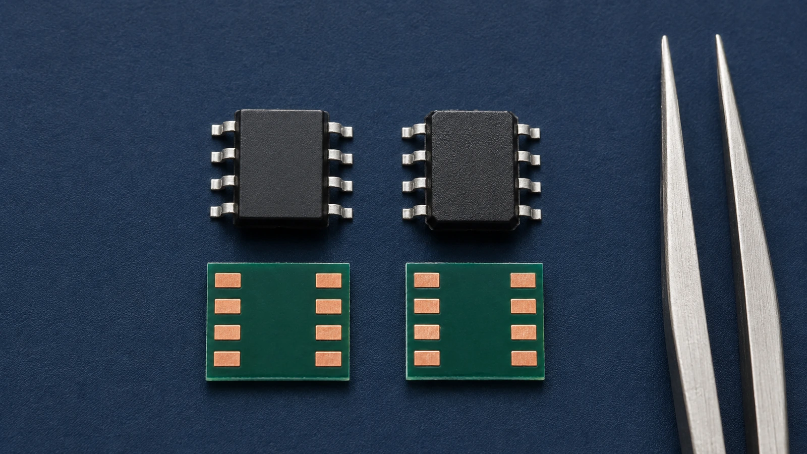
Package compatibility means the proposed body, terminals and assembly features match the PCB land pattern and production process. Compare the package drawing, body dimensions, lead or ball pitch, terminal shape, height, exposed-pad geometry, orientation and pin-1 convention.
Similar package names do not guarantee identical dimensions. Vendor-specific tolerances, thermal pads, lead spans and recommended land patterns can differ. Check the actual mechanical drawing against the existing footprint rather than relying on labels such as QFN-32 or SOT-23 alone.
Pinout compatibility
The same package can contain a completely different pinout. Compare every pin number and function, including power and ground pins, multifunction pins, no-connect pins, reserved pins and exposed-pad connections.
An NC pin on one device may be reserved or internally connected on another. Tying it to a net because the original allowed that connection can create failure. Confirm required pull-ups, strapping pins and power sequencing as part of the pin review.
Electrical ratings and operating behavior
Electrical equivalence depends on the device category and circuit conditions. Compare operating voltage, current, power, tolerance and absolute maximum ratings, then examine parameters that actually affect the design. Relevant examples include capacitor ESR and leakage, MOSFET RDS(on) and gate threshold behavior, regulator dropout and stability requirements, oscillator accuracy, amplifier bandwidth or noise, and digital input thresholds.
Absolute maximum ratings are survival boundaries, not recommended operating points. An alternate should preserve adequate margin across temperature, tolerance and transient conditions. Do not approve a part because one headline rating is higher while a less visible operating parameter is worse.
Timing and interface compatibility
Timing review is necessary when the component participates in clocking, logic, communication or feedback. Relevant checks may include propagation delay, maximum clock rate, setup and hold time, rise and fall behavior, interface voltage, logic thresholds and supported protocol modes.
These checks are not universal for passives or simple electromechanical parts. Apply them where the circuit function makes them material, and validate system timing rather than comparing unrelated maximum values.
Passive-component substitutions
For resistors, compare resistance, tolerance, temperature coefficient, power rating, voltage rating, package and pulse capability where relevant. A same-value resistor can still be unsuitable in a precision, high-voltage or surge position.
For capacitors, compare capacitance at the intended bias and temperature, tolerance, voltage rating, dielectric type, ESR, ESL, ripple current, package and polarity. Nominal capacitance alone can hide large differences in effective capacitance or loss.
For inductors, compare inductance, tolerance, current ratings, saturation behavior, DC resistance, self-resonant behavior, core characteristics and package. The required subset depends on whether the part is used for power conversion, filtering or signal conditioning. This review establishes substitution safety without replacing a full passive-selection study.
Semiconductor substitutions
A semiconductor alternate should preserve the function, pinout, electrical performance, thermal capability, package and lifecycle needed by the design. Integrated circuits may also depend on startup behavior, external compensation, programming or firmware.
Not every semiconductor change requires redesign. A verified pin-compatible alternate may be approved through documented comparison and validation. A device with different pins, peripherals or support circuitry should be treated as a redesign candidate, not forced into a drop-in category.
Connectors and electromechanical parts
Connector equivalence requires the mating interface, keying, pinout, current and voltage ratings, mounting method, retention features, board footprint and mechanical envelope to match the product. Contact plating, environmental rating and insertion-cycle capability may matter for repeated use or harsh service.
Check keep-outs and the complete mated assembly. A connector that solders to the board can still interfere with an enclosure or accept the wrong mating part.
Firmware and software dependencies
Firmware review is required when software identifies, configures, calibrates or communicates with the device. Compare device IDs, register maps, default states, initialization sequences, drivers, timing and calibration data.
Firmware changes are not universal. A passive part or transparent analog replacement may have none. Where a dependency exists, define the supported device variants, regression tests and production programming controls before approval.
Thermal compatibility
Thermal compatibility means the alternate can keep junction or operating temperature within its permitted range in the actual board and environment. Compare power dissipation, package thermal data, exposed-pad requirements, heatsinking, copper area, airflow and ambient conditions.
Datasheet thermal resistance values depend on test conditions and should not be treated as constants for every PCB. A smaller package or different exposed pad can require a layout change even when electrical ratings appear adequate.
Qualification and certification impact
A component change can affect customer approval, safety or regulatory documentation, and industry-specific controls for medical, automotive, aerospace or other qualified products. The impact depends on the part’s function, the approved design baseline and the applicable program requirements.
Recertification is not automatically required for every alternate, but the question should be reviewed by the responsible engineering and compliance owners. Retain the comparison, approval and validation evidence needed by the project.
When does a substitute require PCB redesign?
A substitute requires PCB redesign when the existing board cannot support its footprint, pinout, power, signals, thermal path or mechanical envelope. Changes may include a new land pattern, rerouted pins, revised support passives, altered power rails, additional decoupling, signal-integrity adjustments or enclosure clearance.
Do not hide these changes inside a purchasing substitution. Route them through schematic and layout control. Excel Circuit’s PCB design and layout service can review the affected circuitry and production files when an alternate is not truly drop-in.
Alternate-component validation workflow
- Define the original function and critical specifications.
- Verify lifecycle and supply status for both parts.
- Compare current manufacturer datasheets.
- Compare package drawings, footprint and pinout.
- Review electrical ratings and operating performance.
- Review thermal and mechanical compatibility.
- Review firmware, driver and programming implications.
- Update the schematic, BOM and PCB files when needed.
- Build a controlled prototype or pilot assembly.
- Test against documented acceptance criteria and relevant corners.
- Record the decision, evidence, approvers and permitted use.
If the original part is already unavailable, first review the broader options in the obsolete and hard-to-find component guide. A prototype or pilot PCBA build can then provide evidence before a production release.
An approval record should state the original and alternate MPNs, affected reference designators, board revision, datasheet revisions, comparison results, unresolved limitations, test evidence and approvers. Specify whether approval covers one build, a restricted quantity or ongoing production. A temporary deviation should not silently become a permanent BOM option.
For example, a regulator alternate may match voltage, current and pins but require a different output-capacitor ESR range. The decision is not simply accept or reject: the engineer can preserve the original capacitor if verified, qualify a supporting-component change, or reject the alternate where the circuit cannot be changed. Record the chosen path and the startup, load-transient and temperature checks needed to validate it.
After technical approval, confirm that the replacement actually reduces supply exposure through BOM-level risk analysis. Sourcing approval must also preserve component provenance and traceability controls; electrical equivalence and authenticity are separate questions.
For thermal comparisons, Texas Instruments’ semiconductor thermal-metrics guidance explains why junction-to-ambient resistance depends strongly on the surrounding system. Use the actual board conditions when interpreting the alternate’s thermal data.
Alternate-component approval checklist
- Electrical: operating conditions, limits, tolerance and relevant performance match.
- Mechanical: body, height, mating features and keep-outs fit.
- Package: dimensions, pitch, land pattern, orientation and assembly process agree.
- Pinout: every functional, power, NC, reserved and exposed-pad pin is reviewed.
- Thermal: dissipation, junction margin and heat path are acceptable.
- Firmware: IDs, registers, drivers, initialization and calibration are addressed where applicable.
- Sourcing: manufacturer, full MPN, lifecycle and realistic supply path are documented.
- Qualification: customer, regulatory and program approvals are checked.
- Validation: test scope, samples, corners and acceptance criteria are defined.
- Documentation: BOM, schematic, AVL/AML and change records reflect the approval.
Information required from the customer
Provide the current BOM, original manufacturer part number, datasheet, schematic and PCB files when redesign may be needed. Also identify approved manufacturers or vendor restrictions, allowed alternates, functional requirements, certification constraints, target quantity, production schedule and test criteria.
Excel Circuit can combine this engineering information with component sourcing and BOM review and turnkey PCBA support. Proposed substitutions remain subject to customer approval and project-specific validation.
Review an alternate before it reaches production
Send your BOM and affected part numbers if you need alternate-component options reviewed for electrical, package and production compatibility. Include the design constraints and test requirements that define a safe replacement.