Contents
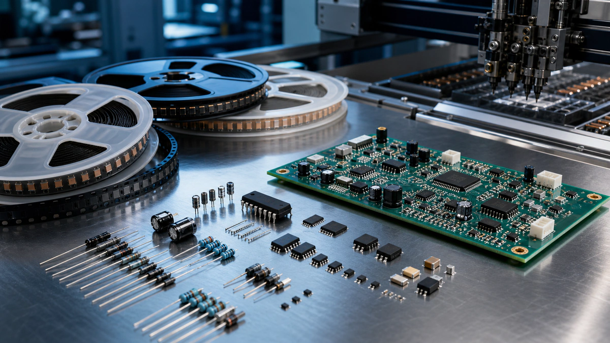
PCB assembly terminology describes the design data, component packages, and production processes used to build an electronic assembly. BOM identifies the required parts; SMD describes surface-mount components; SMT describes the surface-mount process; and DIP describes a common through-hole package style.
What Is a BOM?
A bill of materials (BOM) is a controlled list of the components required to build an assembly. A production BOM should include reference designators, quantity, manufacturer, manufacturer part number, value or description, package or footprint, DNP status, approved alternatives where permitted, and revision information. See how to create a PCB assembly BOM.
What Is SMT?
Surface-mount technology (SMT) is an assembly method in which components are mounted to pads on the PCB surface. The typical process includes solder-paste printing, solder-paste inspection, component placement, reflow, optical or X-ray inspection, and electrical or functional testing.
What Is an SMD?
A surface-mount device (SMD) is a component designed for surface mounting. Resistors, capacitors, QFN, BGA, SOIC, and many connectors are available as SMDs. SMT is the process; SMD is the component.
What Are DIP and THT?
A dual in-line package (DIP) has two parallel rows of leads and is often inserted through plated holes. Through-hole technology (THT) is the broader assembly method for leaded components inserted through the PCB. Not every THT component is a DIP.
PCB vs PCBA
A printed circuit board (PCB) is the bare board containing conductive patterns and insulating materials. A printed circuit board assembly (PCBA) is the PCB after components are mounted and soldered. Manufacturing the bare PCB and assembling the PCBA are separate but connected production stages.
Files Used for Assembly
Assemblers normally require a BOM, pick-and-place file, fabrication data, assembly drawings, polarity information, and project-specific test or workmanship requirements. The pick-and-place file guide explains coordinate and rotation data.