Contents
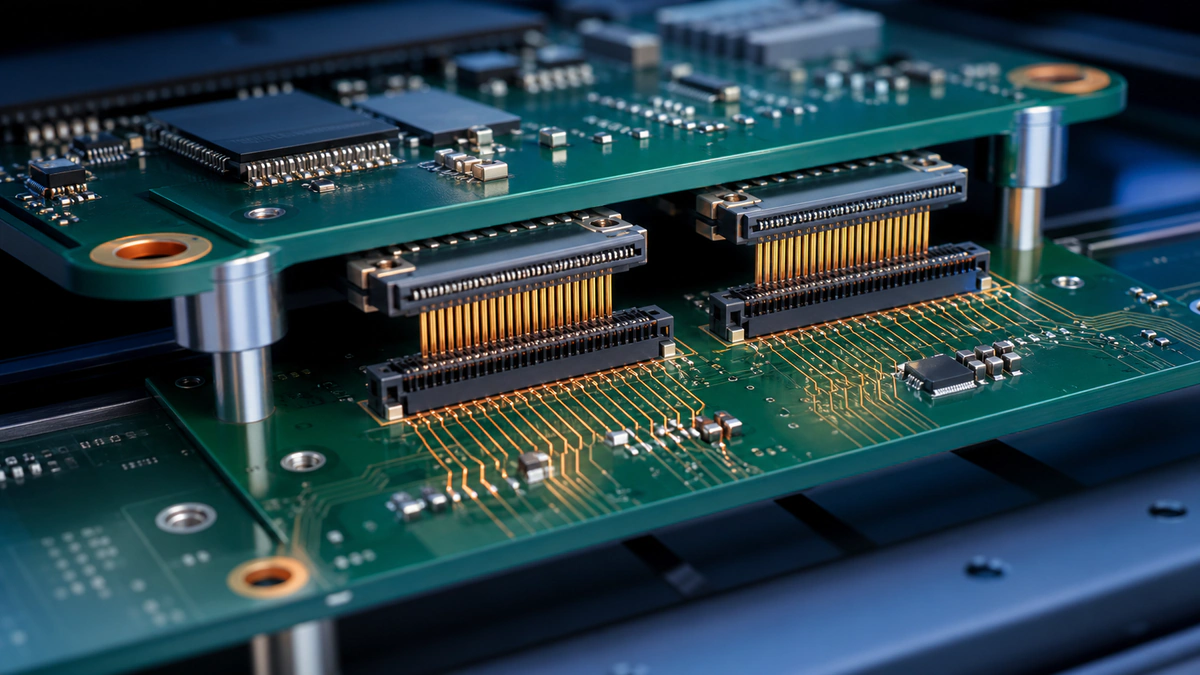
A board-to-board connector joins two PCBs through a controlled mechanical and electrical interface. Selection must coordinate pitch, pin count, current, voltage, signal bandwidth, stack height, mating direction, retention, environment, assembly process, and product lifecycle; choosing by pitch alone can create electrical or mechanical failures.
Define the Connection First
List signal groups, power and ground contacts, current per contact, voltage, interface speed, shielding or ground needs, hot-plug requirements, and unused pins. Separate nominal values from worst-case conditions, including temperature rise and simultaneous-current derating.
Pitch, Pin Count, and Stack Height
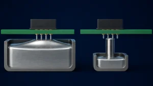
Smaller pitch saves area but reduces routing and inspection access and may narrow manufacturing tolerances. Stack height must include connector mated height, PCB thickness, tolerances, standoffs, enclosure constraints, and allowable compression or movement.
Current, Voltage, and Contact Resistance
Current ratings depend on the number of energized contacts, ambient temperature, conductor size, PCB copper, and permitted temperature rise. Voltage selection must consider creepage, clearance, pollution environment, altitude where applicable, and the connector manufacturer’s qualification data.
High-Speed Signal Integrity
At high data rates, evaluate differential impedance, insertion loss, return loss, crosstalk, ground-contact assignment, launch geometry, reference continuity, and connector models. The connector and PCB launch form one channel; a high-speed part number cannot compensate for a poor breakout. For display modules, LCD and touchscreen PCB design adds interface, ESD, and flex-cable constraints to that launch.
Mechanical Reliability
Check mating cycles, insertion and extraction force, retention, vibration, shock, fretting risk, wipe length, polarization, keying, and tolerance stack-up. Floating connectors can absorb some alignment error, but the permitted offset must come from the supplier specification.
PCB Layout and Assembly
Confirm courtyard, pick-and-place access, solder-joint inspection, stencil requirements, coplanarity, board support, connector keepouts, and rework access. Route high-speed pairs with continuous references and place sufficient ground contacts near critical signals. Connector placement should then be reviewed within the wider PCB layout optimization process.
Selection Checklist
Compare manufacturer lifecycle status, lead time, second-source strategy, drawings, 3D models, qualification reports, packaging, and assembly guidance. Use the high-speed PCB design service when the connector is part of a controlled channel.