SMT tombstoning occurs when one end of a two-terminal component lifts during reflow because soldering forces become unbalanced. The component may stand upright or remain partly raised, leaving an open or unreliable connection. Pad geometry, unequal paste deposits, wetting behavior, placement, thermal gradients, reflow timing and surface condition can all contribute.
The corrective action should follow the evidence. A repeated defect at one location suggests a different investigation from a problem appearing across many components after a process change. Do not assume that adding paste or changing the oven profile will solve every case.
| Possible contributor | Possible mechanism | Evidence to compare | Corrective direction |
|---|---|---|---|
| Unequal deposits | Different contact or wetting behavior at the ends | Paste height, volume and position on both pads | Review apertures and print repeatability |
| Pad asymmetry | Different wetting geometry | Repeated reference or orientation pattern | Check the actual land pattern |
| Placement offset | Unequal engagement with the deposits | Pre-reflow position and rotation | Review placement data and setup |
| Thermal imbalance | The two ends wet at different times | Location, copper connections and measured heating | Review layout and assembly profile together |
| Poor solderability | One surface wets differently | Component/PCB lots and joint condition | Investigate storage, handling and surface condition |
What Does Tombstoning Look Like?
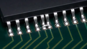
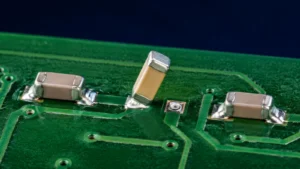
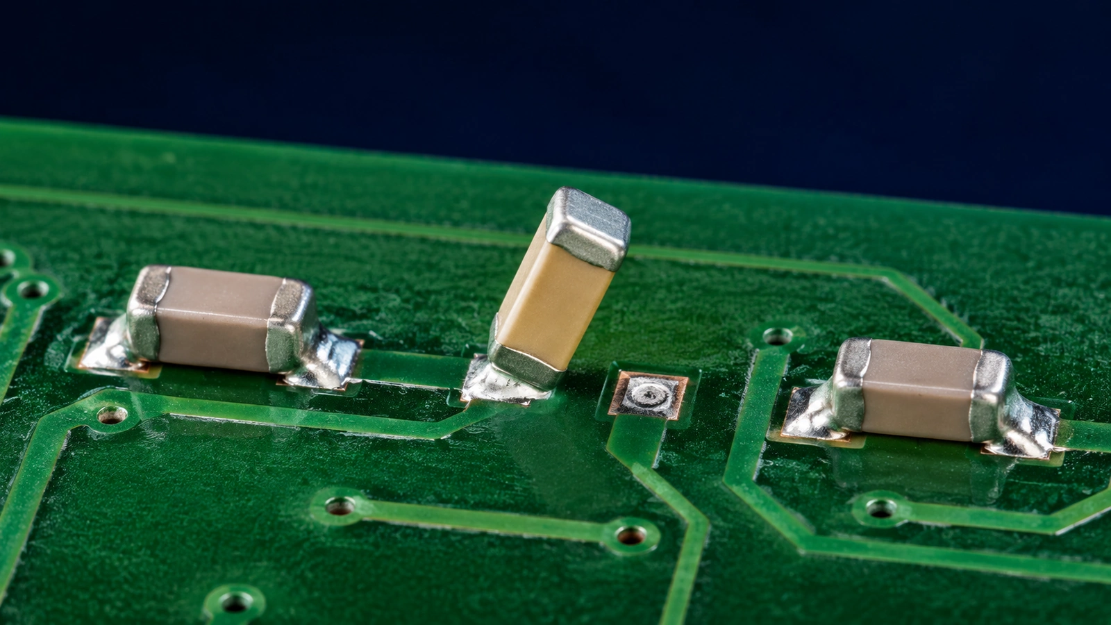
Tombstoning is an end-lifting defect, most commonly associated with small two-terminal resistors and capacitors. One termination remains near or attached to its pad while the other rises away from the intended joint.
The part need not stand perfectly vertical. Partial lifting can still interrupt the connection or leave an unacceptable joint. Record the actual condition rather than rejecting the diagnosis because the component is only tilted.
Distinguish a reflow-induced lift from a component that was missing, misplaced or mechanically disturbed before heating. Pre-reflow images and process records help establish when the change occurred. The defect name describes the result; it does not identify which process variable caused it.
The Practical Physics: Wetting Forces and Timing
Molten solder wets the component terminations and pads, producing forces that can move a small component. When the two ends engage differently or wet at different times, those forces may become unbalanced enough to rotate and lift the part.
Indium’s explanation of tombstoning describes this unequal-wetting mechanism. The useful production lesson is to compare both ends: their geometry, paste contact, thermal history and solderability.
A thermal difference can create a timing difference, but so can unequal surface condition or deposits. Conversely, a layout feature that appears thermally asymmetric is not proof that it caused the observed lift. Use the mechanism to form a testable hypothesis, then look for supporting measurements.
Pad Geometry Should Support Balanced Joints
The land pattern should provide compatible wetting geometry at the two terminations. Unequal pad shapes, spacing errors or a footprint intended for a different package can create an imbalance before process tuning begins.
Verify the exact component ordering code and manufacturer land-pattern guidance. Compare the released artwork with the fabricated pads where possible. A visually similar component body does not guarantee identical termination geometry.
Review both solderable pad geometry and surrounding features. Copper connections can change heating even when the exposed pads look symmetric. Solder-mask registration or local contamination can also change the usable solderable area. Avoid publishing or applying one pad dimension to every component size and supplier.
Compare Paste Deposits Before Changing the Stencil
Balanced paste deposition supports similar contact conditions at both ends. Compare measured height, volume, area and position rather than judging only whether both pads contain paste.
A consistent difference may originate in the aperture design. An intermittent difference may instead involve release, contamination, board support, stencil contact or a printing interruption. Inspect the aperture and the deposit history before concluding that a new thickness is needed.
The stencil thickness and aperture review guide explains the printing-design choices. For a tombstoning investigation, focus on the affected pad pair and whether its two deposits repeatedly differ. Do not reproduce a complete stencil redesign when the evidence points to one inconsistent feature.
If a paste change is proposed, review it with the material and process owners. Different wetting behavior may alter the defect tendency, but changing materials without confirming printing and reflow compatibility can introduce another problem.
Placement Must Engage Both Terminations Consistently
Centering and rotation determine how the component contacts the paste deposits before reflow. A part shifted toward one end may begin heating with unequal termination engagement.
Check actual pre-reflow placement against the intended position. Review board fiducials, package recognition, pickup stability and the placement program when the pattern suggests a positional bias. Do not rely solely on the nominal Pick and Place coordinates.
Placement height and pressure can matter where the component sits unevenly or displaces paste. The correct settings depend on the component and equipment. Increasing pressure is not a universal correction and can create different assembly risks.
Compare affected and unaffected components using the same package and setup. That comparison can help separate a general placement issue from a board-location-specific interaction.
Reflow and Thermal Imbalance Affect Wetting Timing
The temperatures experienced by the two ends can differ because of local copper, nearby thermal mass, board position or heating conditions. If one end reaches effective wetting conditions first, the component may experience unbalanced forces.
Measure the relevant assembly behavior rather than using oven zone settings as a substitute for a profile. A recipe describes the equipment settings; it does not show the temperature at every joint on the loaded board.
Review orientation and location patterns, including whether the same end tends to lift relative to travel direction or a nearby copper feature. Such patterns guide the investigation but do not establish a cause on their own.
Use the paste supplier’s guidance and component limits when evaluating profile changes. A change intended to reduce thermal mismatch must still meet the needs of the whole assembly. There is no single ramp, soak or peak setting that prevents tombstoning on every board.
PCB Layout Can Create Unequal Thermal Paths
A small passive connected to a large copper area at one end and a narrower connection at the other may experience different heating behavior. Direct plane connections, unequal copper coverage and nearby large components deserve attention.
Review those features with electrical requirements intact. A proposed thermal relief or routing change must still satisfy current, voltage-drop and signal requirements. Making the copper visually symmetric is not automatically the correct design solution.
Where the layout is fixed, determine whether the process has an adequate operating window. Where a revision is possible, compare a controlled geometry change with the process evidence. The DFA responsibilities within the pre-production review help assign this work between design and assembly teams.
Component and PCB Surface Condition Can Change Wetting
Oxidation, contamination or inconsistent termination condition can cause one end to wet differently from the other. Review component and PCB lots when the defect begins with a material change or appears inconsistently despite stable setup.
Check traceability, handling and storage records, then compare suspect and known-good material under an agreed evaluation. A photograph alone cannot establish solderability, and adding flux indiscriminately does not identify the source of the problem.
Moisture or storage history should be investigated only where it is relevant to the material and observed condition. Do not label all tombstoning as a moisture defect or prescribe an unverified baking cycle. Follow the applicable component and material guidance.
A Root-Cause Workflow for Tombstoning
Preserve the original evidence and identify where the affected build differs from a stable one. Reworking every lifted part before recording the pattern can remove useful clues.
- Map the defect. Record reference designators, package, lifted end, board location, side and lot. Include how many relevant components were inspected, not just the number of failed boards.
- Compare orientation and location. Look for repeated behavior across the panel, travel direction or neighboring copper features.
- Examine the print. Compare both pads using available paste measurements or pre-placement images. Check whether the imbalance repeats.
- Review pad geometry. Match the component, artwork and actual board condition. Separate exposed-land differences from copper thermal differences.
- Verify placement. Compare intended and measured centering, rotation and contact with the deposits before heating.
- Evaluate thermal behavior. Review the actual profile and the relevant local heating assumptions.
- Check solderability evidence. Compare material lots and surface condition where the earlier checks leave uncertainty.
- Run a controlled corrective trial. State the hypothesis, changed variable, inspection method and acceptance basis before the trial.
If two changes must be introduced together, record that limitation rather than claiming the result proves either one individually. A successful short run is useful evidence but may not cover restart conditions, other panel positions or later material lots.
Separate containment from correction. Segregating affected assemblies and applying an approved rework process can protect the next operation, while root-cause work addresses recurrence. A repaired joint is not evidence that the original manufacturing cause has been removed.
Prevention Controls to Carry Into Repeat Production
Prevention means maintaining the conditions that produced acceptable results, not relying on a one-time adjustment.
- Land pattern: use the correct package definition and review symmetry with copper connections.
- Stencil: keep the accepted aperture revision and paired-deposit intent under control.
- Printing: monitor relevant deposit characteristics and investigate feature-specific drift.
- Placement: maintain validated position, rotation, height and pickup settings.
- Reflow: retain the approved profile and reassess changes to loading or construction.
- Materials: preserve traceability and appropriate handling conditions.
- Monitoring: define the response when the same reference or pattern reappears.
Inspection should feed the process review rather than merely count repaired boards. The assembly inspection and testing guide explains method coverage; visual or AOI findings still need an engineering interpretation. A functional pass does not establish that every marginal joint is acceptable.
Close the corrective action with evidence from the affected feature and a check for unintended effects elsewhere. For example, a paste reduction that reduces lifting must not leave an unacceptable joint volume. Retain the approved settings and the reason for the change so the next build does not return to the earlier setup.
Information Required From the Customer
A useful review connects the defect image to the design and process that produced it. Provide:
- PCB Gerber or ODB++ data and the relevant revision.
- Paste layer, existing stencil details and print measurements if available.
- BOM with exact component part numbers and package information.
- Pick and Place data and assembly drawing for the affected side.
- Defect photos identifying reference designators and the lifted end.
- Pre-reflow placement or print images where available.
- Measured reflow profile and relevant process-change history.
- Build quantity, affected quantity, panel locations and component/PCB lot information.
Identify what is known and what is only suspected. A useful submission might say that one resistor location lifted on several panels after a stencil revision, while the paste measurements are unavailable. That is more actionable than a claim that the oven is at fault without supporting evidence.
Review the Affected Assembly Before the Next Build
Excel Circuit combines in-house PCB design engineering with in-house SMT assembly support. A tombstoning review can connect land patterns, printing inputs and process evidence without assuming one universal remedy.
Send the affected PCB data, BOM, placement file and defect photos for an assembly-process review. Include the relevant references, lots and recent changes so the investigation can focus on the observed pattern. Submit your tombstoning review data.