Mixed SMT and through-hole assembly normally combines solder paste printing, SMT placement and reflow with through-hole insertion and secondary soldering. The exact sequence depends on board design, component type, assembly side, soldering method, temperature sensitivity, quantity and inspection/test requirements. Treat a typical route as a planning starting point, not a universal instruction for every mixed-technology PCB.
The main question is whether each operation leaves the next operation possible. A connector installed too early may block a fixture, while a heat-sensitive part installed too late may require a separate soldering and inspection step.
| Stage | SMT components | Through-hole components | Main consideration |
|---|---|---|---|
| Paste printing | Normally required for reflow | Only for a suitable paste-in-hole route | Stencil and deposit compatibility |
| SMT placement | Placed onto paste | Separate insertion unless suitably packaged and processed | Alignment and access |
| Reflow | Forms intended SMT joints | Qualified intrusive-reflow cases only | Thermal compatibility |
| THT insertion | Existing parts must be protected | Manual or automated insertion as appropriate | Fit, polarity and support |
| Secondary soldering | Protect or process according to the approved route | Wave, selective or hand soldering | Access and thermal exposure |
| Inspection | Check relevant joints and placement | Check seating and soldered connections | Coverage before features become hidden |
| Test | Verify the complete assembly under the defined test plan | Electrical and functional evidence | |
SMT and Through-Hole Assembly Use Different Attachments
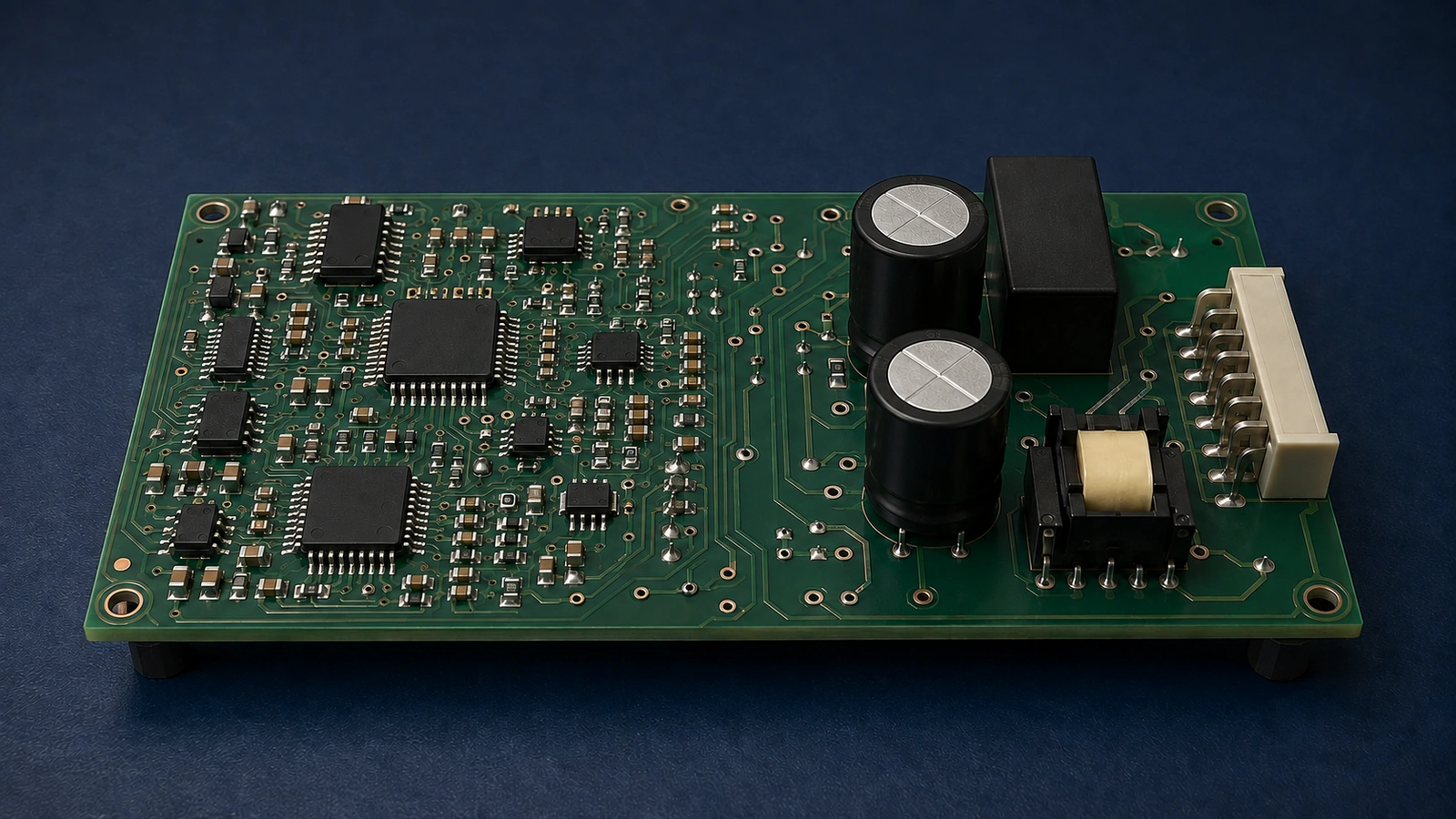
Surface-mount components attach to lands on the PCB surface. Through-hole components have leads or pins inserted through the board, with soldered connections formed at the intended plated holes. A mixed assembly uses both attachment styles because the selected components and product interfaces require them.
The package choice affects more than the placement machine. It changes material presentation, insertion, support, solder access and inspection. Distinguish soldered through-hole parts from press-fit connections, which use a different attachment process. The presence of a pin in a hole does not by itself mean that the connection belongs in the soldering route.
Why Mixed Assembly Remains Useful
Mixed assembly is common when connectors, transformers, relays, large electrolytic capacitors or specialized power components coexist with compact surface-mount circuitry. A required connector may only be available in a leaded configuration, or a mechanically loaded part may need a specific mounting arrangement.
Through-hole attachment is not universally more reliable. Reliability depends on the component, board, joint, mechanical loading and operating environment. Evaluate the actual interface and available packages before changing technology. Replacing a suitable leaded component solely to eliminate one operation can introduce sourcing, electrical or mechanical problems that outweigh the apparent process simplification.
A Typical Mixed-Assembly Sequence
A common route assembles the reflow-compatible SMT population first, inspects it, then inserts and solders the through-hole population. This keeps large leaded components out of early printing and placement operations, but it is only one route.
- Print solder paste: use the approved paste layer and stencil for the side being assembled.
- Place SMT components: verify materials, orientation and the placement program.
- Reflow: form the intended joints using a profile established for the assembly.
- Inspect the SMT stage: identify placement and joint concerns while access is available.
- Insert through-hole parts: confirm polarity, seating and any required support.
- Complete secondary soldering: use the approved wave, selective or hand-soldering route.
- Inspect the completed assembly: check the new joints and features potentially affected by the later operations.
- Test: apply the released electrical and functional procedure.
Some products require a different order, multiple secondary operations or qualified through-hole reflow. Put those exceptions into the route documentation. The broader turnkey PCB assembly workflow covers sourcing, production preparation and shipment around these shop-floor stages.
Double-Sided SMT Adds a Retention and Access Review
Double-sided SMT usually requires planning for both reflow passes before through-hole insertion. Decide which population is assembled first and how the already fitted parts will behave when the board is inverted and reheated. Component retention depends on the package, joint geometry and process; do not assume every part remains secure without review.
Review heavy or tall devices, board support and the access needed to print and place the second side. The second reflow pass also contributes to the assembly’s thermal history. Later through-hole insertion and soldering must protect the populated underside, including parts that may interfere with a pallet or nozzle. If a component needs a special retention method, document and validate it instead of treating adhesive or another accommodation as an automatic requirement for all double-sided boards.
Plan Through-Hole Insertion as a Controlled Operation
Through-hole insertion may be manual or automated, depending on component format, geometry, quantity and equipment. Confirm lead forming, hole compatibility, insertion direction, polarity and the required seated height. A part should not need unexplained force or uncontrolled lead bending to fit the released board.
Check connector keying and mechanical alignment before soldering makes correction more difficult. Tall or heavy components may need support during handling and soldering. Define that support without imposing unintended load on neighboring parts. If lead trimming or forming is needed, specify its place in the sequence and review component restrictions; otherwise two operators may produce different physical assemblies from the same drawing.
Where Wave Soldering Fits the Route
Wave soldering passes the intended solder side over a broader solder wave after fluxing and preheating. It can suit accessible through-hole populations and compatible layouts. On mixed boards, exposed bottom-side SMT and other protected features need deliberate design and process planning.
A pallet or masking arrangement may isolate areas that should not contact solder, but it also changes access and heating. Confirm that the proposed arrangement can expose the required through-hole joints without compromising neighboring parts. This stage should be selected from the board geometry and material restrictions, not inserted into the flow simply because the board contains through-hole leads.
Where Selective Soldering Fits the Route
Selective soldering targets specific through-hole joints or areas, often using a controlled local solder nozzle. It can accommodate mixed populations that are awkward for broad solder exposure, provided the nozzle and associated tooling can reach the joints.
Review underside obstacles, lead protrusion and the path between joint groups. Local control does not eliminate the need for flux, preheat and process validation. The selective-versus-wave process comparison addresses the choice in detail; this mixed-assembly route must identify when the chosen process occurs and what must be protected before it starts.
Hand Soldering Can Be an Appropriate Planned Step
Hand soldering may be practical for prototypes, very small quantities, isolated connections or features that are difficult to reach by the proposed automated method. It is also used for authorized repair and rework. It is not automatically an inferior joint-forming method.
Its suitability depends on access, operator control, materials and the required inspection evidence. Plan the instructions, thermal restrictions and acceptance requirements as carefully as for another process. Distinguish a deliberately selected manual step from an unplanned repair loop caused by a poor layout. Repeated manual intervention may signal that the design or process route needs reconsideration.
Pin-in-Paste Can Combine Steps for Suitable Parts
Pin-in-paste, also called intrusive reflow or paste-in-hole, uses solder paste around or in a plated hole and a suitable inserted lead to form the connection during reflow. It may remove a separate soldering step for eligible components, but it does not make every through-hole part reflow-compatible.
Check the component’s approved reflow exposure, package construction, lead geometry and required solder volume. The hole, pin and stencil strategy must be reviewed together. Samtec’s paste-in-hole guidance directs designers to connector-specific footprint and aperture recommendations rather than one universal geometry.
Confirm that insertion and paste displacement leave enough material for the required joint without interfering with adjacent features. Evaluate the actual printed result and soldered sample before relying on the simplified route. A component family name alone is not evidence that a particular variant supports this process.
Track Thermal Compatibility Across the Whole Build
Thermal compatibility concerns every exposure the component and assembly will experience, not just the first oven pass. Review reflow-sensitive plastics, connectors and other parts against supplier guidance, including whether the permitted exposure refers to the component body or its solderable leads.
Installing a sensitive part after SMT reflow may be necessary, but the subsequent soldering method still transfers heat into the leads, board and nearby structures. Consider both double-sided reflow and later local heating when evaluating the route. Do not copy a solder-pot setting into a component temperature limit; these are different measurements. Manufacturing should establish the process against the actual board and specified restrictions.
Check Layout Against Each Later Operation
Layout review should follow the sequence from printing through final test. Examine through-hole pad access, bottom-side keepouts, neighboring component heights and the space occupied by fixtures or nozzles. Check the travel path as well as the final soldering position.
The PCB assembly DFA checklist translates those concerns into design-review items. Use it before placement is frozen. If a connector blocks inspection after insertion, the route may need an earlier inspection gate or a layout change. If a pallet covers a test point, specify whether testing happens after the pallet is removed and whether the assembly is still adequately supported.
Inspect at the Stage Where Evidence Is Available
Inspection should check the joints created by each major stage and identify damage introduced later. AOI may support visible SMT checks; visual inspection addresses accessible through-hole seating and joint features. X-Ray is relevant where hidden joints or other structural questions require it, according to the product and inspection plan.
Electrical and functional tests provide different evidence from optical or X-Ray observations. Use the assembly inspection and testing-method guide to define coverage. A passed intermediate inspection does not release the completed assembly if later insertion, soldering or handling can affect it. Record which stage found a defect so the team can investigate the appropriate operation rather than treating every final failure as a reflow problem.
Understand Mixed-Assembly Cost Drivers
Mixed-assembly cost is influenced by extra setup, insertion labor, fixtures, masking, secondary soldering and inspection. Low-volume work may be particularly sensitive to setup and changeover effort, while repeat builds depend on the stability and efficiency of the entire route.
Compare complete process plans. A route with fewer machine operations may require more manual preparation, or a fixture may simplify soldering while adding handling. The PCBA cost-driver breakdown explains the broader quotation context. Provide quantities, variants and expected repeat demand so engineering can assess options without relying on an invented volume threshold or savings percentage.
When Mixed Assembly Makes Sense
Mixed assembly makes sense when the required component functions and interfaces justify both attachment technologies and a feasible route exists. Consider mechanical loading, connector format, package availability, current-handling requirements and the constraints of the complete product.
Review quantity and reliability requirements alongside process access. A leaded power component may be appropriate electrically but need a different placement to enable soldering and inspection. Conversely, a surface-mount alternative may simplify the route only if its ratings, availability and mechanical role are acceptable. Make the technology decision with design, sourcing and manufacturing together.
Information Required From the Customer
Provide controlled Gerber or ODB++ data, BOM, Pick and Place file and assembly drawing. Identify the through-hole population separately where it helps clarify insertion, polarity, special seating or support. Include component datasheets, mechanical constraints, target quantity and any soldering restrictions.
Add test requirements and identify parts that cannot follow the normal reflow or secondary-soldering route. State whether alternative packages or layout changes can be considered. These inputs let the team develop a process sequence that can be quoted and repeated instead of discovering a late-installed component problem on the production floor.
Review the Mixed-Technology Route Before Production
Excel Circuit combines in-house SMT assembly, design engineering and component sourcing with qualified PCB manufacturing resources and turnkey PCBA coordination. Through-hole and secondary assembly support should be confirmed against the specific job; this process explanation does not imply ownership of a particular soldering machine.
Submit your mixed-assembly process inputs with the BOM, PCB data and assembly drawing. Include the through-hole part list and thermal restrictions so the SMT/THT sequence can be reviewed before quotation or production.