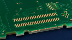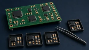
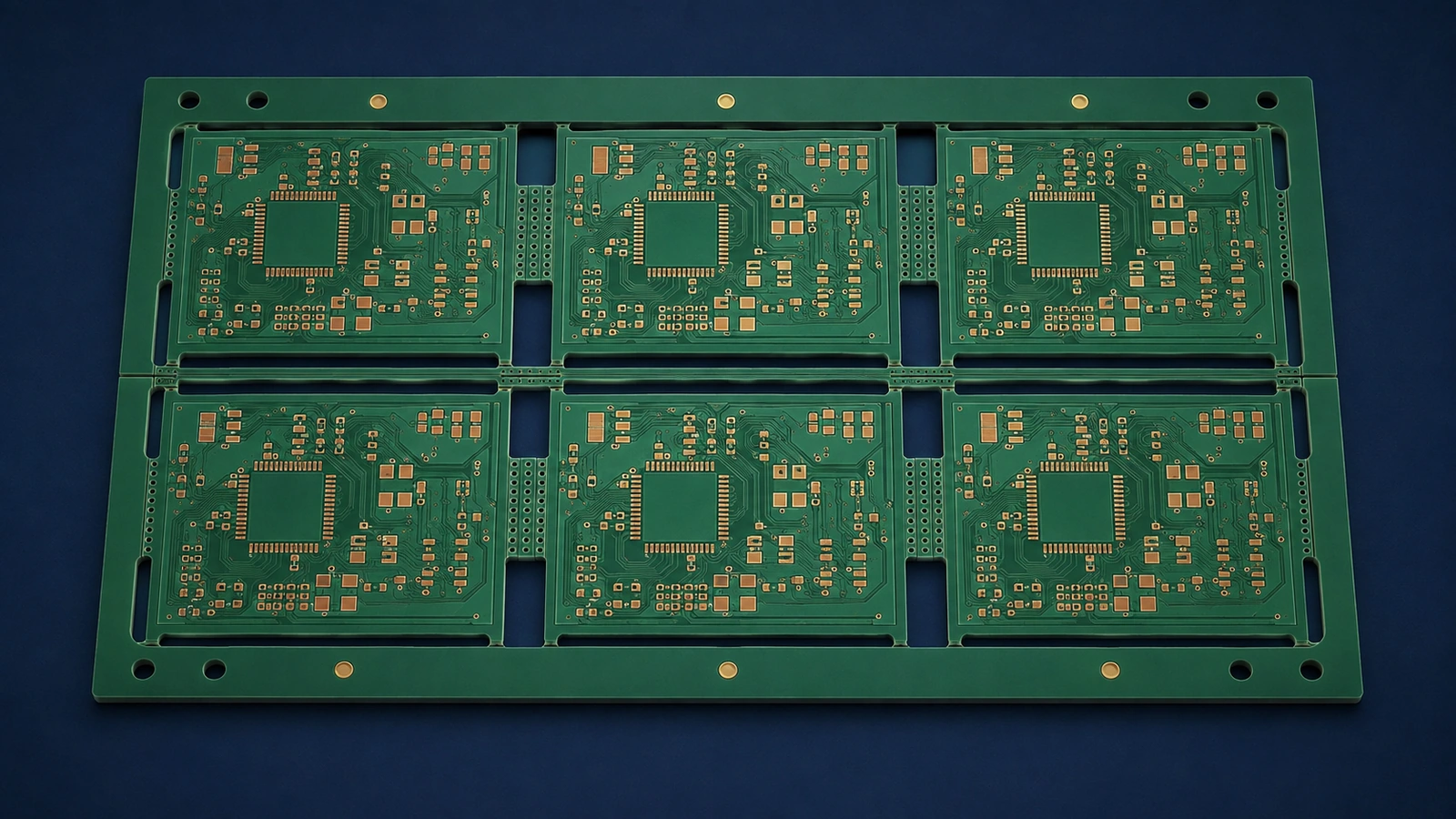
PCB panelization groups boards into a manufacturing or assembly panel to improve handling, SMT processing, tooling, throughput and consistency. Choose the array and separation method around the board outline, component clearance, mechanical strength, depanelization method, assembly process and required finished edge quality.
V-scoring usually suits compatible straight edges, while tab routing provides more freedom for irregular outlines. Perforated breakaway tabs, commonly called mouse bites, are a tab feature rather than an entirely separate panel architecture. The best choice is the one that the fabricator and assembler can produce, handle and separate without violating the product’s requirements.
| Method | Typical fit | Main advantage | Main limitation |
|---|---|---|---|
| V-scoring | Suitable straight edges and repeated rectangles | Can support efficient separation | Score-line access, residual material and edge constraints |
| Tab routing | Irregular outlines and selected attachment points | Flexible board geometry | Routing space, retained tabs and removal access |
| Mouse-bite tabs | Perforated breakaway tabs within a routed panel | Can simplify controlled tab removal | Stress and edge remnants need review |
| Mixed method | Panels with different edge requirements | Combines methods where useful | More complex tooling and separation planning |
What is PCB panelization?
A fabrication panel is the working format used by the PCB manufacturer for its production processes. An assembly panel is the array presented to the assembler for handling and component assembly. The fabricator may place several customer arrays inside a larger manufacturing panel, so these formats are related but not always identical.
An assembly array can contain repeated boards, connecting material and tooling rails. Its orientation and references must remain consistent with assembly data. Do not approve an array solely because it uses fabrication material efficiently; it must also fit the assembly line, fixtures and separation process.
State whether the order requires individual boards or boards retained in an approved array. A drawing of repeated outlines without attachment and separation details is not yet a complete panel requirement.
Why panelization matters for PCBA
Panelization gives equipment a manageable structure for conveyor transport, stencil printing, pick-and-place, reflow and inspection. Tooling holes and fiducials can help locate the array, while rails provide handling surfaces that do not consume functional board area.
The same array must remain usable through the intended sequence. A rail that works for printing may become obstructed by an overhanging connector later. A panel that is easy to load may flex under component weight or during separation.
Review these relationships alongside the PCB assembly DFA checklist. That guide owns general assembly access and alignment; the panel decision establishes where boards, rails, references and breakaway features sit relative to each other.
V-scoring
V-scoring forms grooves along intended separation lines while leaving material to hold the boards together. It commonly suits straight-line layouts, but allowable line paths and special scoring options depend on the fabricator and equipment. Do not assume an arbitrary internal or interrupted line can be scored.
Remaining material controls the balance between panel strength and separation effort. Board thickness, construction, groove geometry and the planned removal method influence the result. There is no universal residual thickness suitable for every board.
Confirm score direction, component and copper clearances, access for separation tools and the required edge condition. The assembler should review whether the populated board can pass through the chosen separation operation. A mechanically convenient score line is unsuitable if a tall part blocks tool travel or the resulting stress threatens the assembly.
Document the finished-board boundary separately from the scoring instruction. This prevents the nominal score line from being mistaken for a complete specification of the final edge.
Tab routing
Tab routing removes material around the board outline while retaining selected bridges that hold each unit in the panel. It accommodates irregular shapes and allows attachment points to be placed where the design can tolerate them.
The routing path needs tool access and space. Tabs need enough strength for handling and assembly, yet they must be removable using the agreed process. Their positions can affect board flex, edge cleanup and access to nearby components.
Show areas where tabs are prohibited, such as locating edges or sensitive component regions. Ask the fabricator and assembler to propose supported attachment locations and a removal sequence. Do not accept automatic tab placement without checking the populated assembly and the final mechanical envelope.
Mouse bites
Mouse bites are perforations in breakaway tabs that create a controlled weakened region. They are often used with routed outlines; they do not replace the need to specify the surrounding route and retained panel structure.
Perforations can make removal easier, including manual separation where qualified, but the remaining edge can require cleanup. Hole pattern, tab geometry and placement must suit the material and approved removal process. A generic hole diameter or pitch is not a reliable production rule.
Agree whether remnants are permitted, where they may project and whether trimming is required. If an edge fits closely against an enclosure, avoid leaving acceptance to a visual description such as clean break. Identify the measurable finished condition and who performs the final operation.
Tooling rails
Tooling rails provide surfaces for conveyor support, gripping, fixtures and panel references. They can carry fiducials, tooling holes or identification without occupying the individual PCB. Their dimensions and locations depend on the equipment and assembly route.
Confirm rail needs on each handling side and throughout double-sided assembly. Consider components that overhang the board, underside features that interfere with supports, and whether any operation needs the rail retained after soldering.
Do not apply one universal rail width. Ask the assembler to define the required usable support area and clearance, then coordinate the resulting array with the fabricator. Also specify when rails are removed: removing them too early can eliminate the references or gripping surfaces required by later operations.
Fiducials and panel alignment
Global panel fiducials provide references for locating the array. Local fiducials may support alignment of particular components or regions where the assembly process requires them. They serve related purposes but should not be assumed interchangeable.
Confirm visibility, surrounding clearance and availability on the relevant assembly side. A reference hidden by tooling, paste, a component or removed rail cannot perform its intended role. Tooling holes provide mechanical location and should also be reviewed against fixture needs.
Maintain a consistent origin, orientation and board-instance mapping between the panel drawing and placement data. Before approving an array revision, ask whether the stencil, assembly program and inspection references must change with it.
Component-to-board-edge clearance
Components near a breakaway edge need clearance for both manufacturing and separation. The relevant envelope includes the component body, leads, solder joints, tool path and support arrangement, not merely the copper footprint boundary.
Overhanging connectors can obstruct a cutter or occupy the space between neighboring boards. Routing or scoring access can also conflict with parts on the opposite side. Supply placement information and component height or overhang where it controls the decision.
Ask the assembler to review the proposed removal direction and fixture contact points. If a component cannot move, the array or separation method may need adjustment. Do not substitute a generic edge-clearance dimension for checking the actual populated geometry.
Depanelization stress
Depanelization can bend the board and transfer strain into components and solder joints. Ceramic capacitors are sensitive to board flex, and BGA or QFN assemblies can also require attention where strain reaches package connections or the supporting board structure.
Review sensitive-component position and orientation relative to expected bending, tab locations and supports. The stress depends on the complete operation, including tooling, cutting direction and how the board is restrained. No method is automatically safest for every construction.
For a critical assembly, request process validation appropriate to the product, potentially including strain assessment and inspection after separation. Avoid approving a method only because an unpopulated sample breaks easily. The populated panel can behave differently because of component mass, stiffness and tool-access restrictions.
Odd-shaped boards
Irregular boards may require routed spacing, additional rails or retained support material to form a manageable array. The support arrangement should hold each unit through processing without placing unwanted tabs on functional edges.
Nesting shapes tightly can improve material use but reduce access or leave a weak structure. Evaluate narrow connections, unsupported regions and heavy components before approving the arrangement. If boards are rotated within the panel, confirm assembly orientation and reference mapping.
Provide the mechanical outline and identify protected edge zones. Let the fabricator propose a manufacturable route while the assembler confirms handling and separation. This coordination matters more than making the array look compact in CAD.
Panelization and SMT assembly
The array must support printing, placement, reflow and AOI as a continuous production sequence. Printing needs suitable support and alignment; placement needs stable references and access; reflow handling must accommodate the populated structure; inspection needs unobstructed views and consistent board mapping.
Check support under thin or heavily routed areas and clearance around components on the underside. Include any secondary insertion, soldering or test operation that occurs before separation. The turnkey PCB assembly process guide explains the broader handoffs in which the array must remain usable.
When changing from individual prototypes to an array, review the process again. The prototype-to-production PCBA guide covers that transition; successful assembly of one loose board does not validate support and separation for the production panel.
Panelization and cost
Panel cost depends on more than material utilization. Routing time, tooling, stencil and fixture requirements, assembly handling, inspection and depanelization labor can change the overall result. A denser array may save material while creating a more difficult assembly or cleanup operation.
Compare alternatives using the complete production route and target quantity. Ask the suppliers which costs arise from the array choice and which remain unchanged. Avoid unsupported formulas or percentage savings: the economical choice depends on equipment compatibility and the product’s edge and stress requirements.
Keep quality constraints explicit during that comparison. A cheaper separation step is not acceptable if it compromises the mechanical interface or requires unplanned rework.
Who should define the panel?
The customer defines product constraints and may supply a preferred array. The fabricator optimizes fabrication within those constraints. The assembler defines the handling, tooling, placement and separation requirements for its production route. Assembly-oriented panel design should be agreed before manufacturing begins.
If the customer supplies a fixed array, identify which details are mandatory and which may be revised. If the supplier proposes the array, require approval of the final drawing before production. Record the revision used for stencils, fixtures, programs and inspection.
Include the approved panel information in the PCB production package. An email saying panelize as usual is insufficient when edge quality, connectors or sensitive components constrain the result.
Panelization design checklist
- Outline: confirm the finished shape, cutouts and protected edges.
- Method: agree V-scoring, routing, perforated tabs or a coordinated combination.
- Rails: confirm handling surfaces and the stage at which they are removed.
- References: approve fiducials, tooling holes, origin and board-instance mapping.
- Components: review edge clearance, overhang, height and underside access.
- Stress: identify sensitive regions, supports and validation needs.
- Direction: coordinate assembly orientation and separation sequence.
- Mechanical acceptance: define allowable remnants, cleanup and finished edge condition.
Use the PCB manufacturing tolerance guide when defining dimensional acceptance after separation. Panelization selects the structure and removal route; tolerance requirements define the finished result that route must deliver.
Information required from the customer
Provide Gerber or ODB++ data, board outline, mechanical drawing, target quantity and assembly-side requirements. Include component placement, overhanging connectors, sensitive parts and any preferred array. Identify depanelization restrictions, edge-quality requirements and downstream assembly constraints.
State whether rails or tabs must remain for testing or delivery and who performs final separation. Where a mechanical interface is critical, provide the mating-part information or acceptance drawing. Ask for one coordinated panel proposal with unresolved questions listed before production release.
Review the panel and breakaway method before production
Excel Circuit combines in-house PCB design engineering and SMT assembly with sourcing and qualified PCB manufacturing resources. Its turnkey PCBA services can coordinate fabrication arrays with assembly handling and production-readiness requirements.
Send your PCB outline, Gerber data and assembly requirements if you need the panel layout and breakaway method reviewed before production. Submit your PCB panelization review inputs.