Contents
A production-ready PCB assembly BOM should identify each component by reference designator, quantity per board, manufacturer, manufacturer part number, value or description, and package or footprint. It should also show DNP or DNI status where applicable, approved alternatives when permitted, and any necessary sourcing notes. Although assemblers may accept different spreadsheet formats, clear part identification, consistent revision information, and unambiguous sourcing instructions reduce quotation questions and production errors.
What Is a PCB Assembly BOM?
A PCB assembly bill of materials, or BOM, is the controlled component list used to prepare, quote, source, and build an assembled circuit board. It connects the released electronic design to the physical materials required for production. Each line normally represents one component type or purchasing item and identifies where that item belongs on the board, how many are used, and which part specification is intended.
During quotation, the BOM helps the assembly supplier estimate component cost, availability, procurement responsibility, and material-related lead-time risks. During component sourcing, it provides the structured part identities and restrictions needed to request the correct items. During assembly preparation, reference designators and build-variant information help the production team relate the component list to placement and assembly data. The released BOM also supports material control by distinguishing installed parts, excluded parts, approved alternatives, and customer-supplied material.
A BOM is not the same as a pick-and-place file. The BOM primarily states what components are required, while placement data describes where applicable SMT components are positioned. Both may be needed as part of an assembly package, but they serve different purposes. A useful BOM therefore needs clear, consistent fields rather than a particular proprietary layout, and it should remain aligned with the schematic, PCB design, and assembly release.
What Information Should a PCB Assembly BOM Include?
The exact PCB BOM format can vary between organizations and assembly suppliers. The following fields provide a practical baseline for a BOM that purchasing, engineering, and production teams can interpret reliably.
| Field | Purpose | Notes |
|---|---|---|
| Reference Designator | Connects each BOM line to PCB component locations | May contain grouped references such as R1, R2, and R5 |
| Quantity per Board | States how many units are installed on one PCBA | Should agree with the listed references and build variant |
| Manufacturer | Identifies the component maker | Can be fixed or flexible according to project policy |
| Manufacturer Part Number | Defines the intended purchasable component | Use approved alternatives separately when permitted |
| Value / Description | Supports engineering and human-readable review | Does not normally replace a specific MPN |
| Package / Footprint | Helps check mechanical and assembly compatibility | Should agree with the selected part and PCB footprint |
| DNP / DNI Status | Identifies references excluded from a build variant | Define the terminology used in the release |
| Approved Alternative | Records a permitted substitute component | Package compatibility alone does not establish equivalence |
| Substitution Policy | Defines whether alternatives may be used or proposed | State approval requirements clearly |
| Sourcing Model | Assigns component procurement responsibility | Supplier-sourced, consigned, or mixed |
| Notes | Communicates limited special instructions | Keep critical part identity in structured fields |
| BOM Revision | Identifies the controlled BOM release | Keep it aligned with the released design package |
Reference Designator
A reference designator identifies a component position in the electronic design and on the PCB. Common examples include R1 and R2 for resistors, C4 for a capacitor, U3 for an integrated circuit, and J1 for a connector. These references allow engineering and assembly teams to connect a BOM line with schematic symbols, PCB footprints, placement information, assembly drawings, and inspection records.
Identical components are often grouped on one BOM line. A single resistor line might list R1, R2, R5, and R8 rather than requiring one row for each physical reference. Grouping is acceptable when the part identity, value, package, fitted status, and other relevant requirements are genuinely the same. The quantity on that line should match the number of installed references for the applicable board variant.
The reference list should come from the released design data and remain consistent with the PCB assembly package. Missing, duplicated, obsolete, or mistyped references create uncertainty about which positions should be populated. When variants share a common PCB, the BOM must also make clear which references apply to the build being quoted or manufactured.
Quantity per Board
Quantity per Board states how many units from a BOM line are installed on one assembled PCB. If a board uses the same resistor at R1, R2, R3, and R4, the Qty / Board value is 4. This value should agree with both the reference designator list and the fitted status for the selected assembly variant.
Do not confuse Qty / Board with the total quantity that must be purchased. For an order of 100 boards, the nominal requirement for that resistor is 400 units, but actual procurement planning may also consider packaging quantities, minimum order quantities, sourcing conditions, and process allowance. Those considerations are project-specific; a BOM preparation guide should not prescribe a fixed percentage of extra components for every build.
Keeping the per-board quantity separate from the requested assembly quantity makes the BOM reusable across prototype and production orders. It also allows the quotation team to calculate material demand without changing the design-controlled component definition.
Manufacturer
The Manufacturer field identifies the company responsible for the specified component. Names such as Texas Instruments, Murata, Yageo, STMicroelectronics, and NXP may appear in real BOMs as ordinary examples of component manufacturers; their mention does not imply a commercial partnership or authorized relationship.
Manufacturer information helps distinguish parts with similar descriptions and supports part-number verification. It is especially useful when multiple manufacturers use different naming systems or offer variants with different ratings, qualifications, packaging, or lifecycle status. The manufacturer name should agree with the manufacturer part number on the same BOM line.
Not every BOM line must always lock one manufacturer. Some projects permit a controlled selection of commodity passive components that meet defined requirements. In that case, the BOM should express the approved manufacturer or substitution policy clearly instead of leaving the sourcing team to infer whether any nominally similar part is acceptable.
Manufacturer Part Number
The manufacturer part number, commonly abbreviated MPN, is one of the most important identifiers in a PCB assembly BOM. A description such as “10 kΩ resistor” communicates a nominal value, but it may not define the package, tolerance, power rating, voltage rating, temperature characteristics, material system, or manufacturer-specific ordering variant. An MPN points to a particular purchasable component definition and helps engineering, purchasing, and inspection teams evaluate the same intended item.
Accurate MPNs reduce ambiguity during quotation and component sourcing support. They allow availability and sourcing questions to be associated with the correct component rather than a generic description. The MPN should be copied carefully, because small suffix differences can indicate a different package, temperature grade, tolerance, packing method, or other variant. Manufacturer and MPN fields should also remain logically consistent.
This does not mean that every commodity passive component must always be locked to one unique MPN. A project may define approved alternatives or a controlled technical requirement for eligible parts. Where flexibility is allowed, record it through the Approved Alternative and Substitution Policy fields. Do not make the sourcing team guess whether a listed MPN is mandatory, preferred, or merely illustrative.
Value or Description
The Value or Description field provides a readable summary of the component. Entries might include 10 kΩ, 100 nF, 3.3 V regulator, MCU, or USB-C connector. This information helps engineers and buyers scan the BOM, compare related lines, and identify obvious inconsistencies between the stated function and the selected component.
A description should support the MPN rather than silently replace it where a specific part is required. Generic terms such as “IC,” “connector,” “crystal,” or “power component” usually omit critical electrical, mechanical, or ordering information. Even a resistor value alone may not communicate tolerance, power, voltage, temperature coefficient, or package.
Use concise descriptions that make review easier, but keep exact part identity in structured manufacturer and MPN fields. If the project intentionally permits a family of equivalent commodity parts, document the acceptance criteria or approved alternatives instead of relying on a broad description.
Package or Footprint
The Package or Footprint field describes the physical form expected by the design and assembly process. Examples include 0402, 0603, SOT-23, QFN, and BGA. For a clear production release, the BOM description should be compatible with the selected MPN, the land pattern used in the PCB design, and the applicable placement or assembly data.
This field is useful for detecting obvious mismatches, such as an MPN suffix that indicates a different package from the PCB footprint. However, an assembly supplier cannot prove that a land pattern is correct from a short BOM package label alone. Pin configuration, dimensions, exposed pads, thermal features, orientation, and manufacturer recommendations may still require review in the source design and component documentation.
If the footprint, reference designators, or release package remain inconsistent, correct the source data through the appropriate PCB design and layout services workflow before production release rather than using the BOM as a substitute for a design change.
DNP / DNI Status
DNP commonly means Do Not Populate, while DNI commonly means Do Not Install. Organizations may use these and related terms differently, but their practical purpose is to identify component references that are intentionally not fitted in a particular assembly variant. A DNP line may still appear in the design database because the same PCB supports another configuration.
Critical assembly exclusions should be explicit in the controlled production data. Do not rely only on an email, verbal instruction, or an unexplained spreadsheet color. A dedicated status field, a defined value such as Yes/No or Fit/Do Not Fit, and consistent reference lists are easier to review and less likely to be lost when files are forwarded.
DNP and DNI should not be described as universally identical across all company workflows. Define the terminology used for the project and make sure the BOM, assembly drawing, and variant information do not contradict one another.
Approved Alternatives
An Approved Alternative field records a substitute component that has already been accepted for the project. Listing the alternative MPN beside the primary part gives purchasing a controlled option when availability, lead time, or order quantity makes the preferred component difficult to obtain.
An alternative should not be considered equivalent simply because it has the same nominal value or package name. Electrical ratings, tolerance, pinout, dimensions, temperature range, qualification, lifecycle, and application-specific behavior may matter. Detailed equivalence assessment belongs in the engineering approval process; the BOM should record the resulting decision clearly.
If no alternative has been approved, leave the field unambiguous and use the substitution policy to state whether the supplier may propose an option for review. Never imply that a supplier may freely substitute parts without the required approval.
Substitution Policy
A Substitution Policy field tells purchasing how to interpret the primary and alternative part information. Three practical states are: approved alternatives only; supplier may propose alternatives for approval; and no substitution. These labels define the decision path without attempting to replace the technical review behind an equivalence decision.
Approved alternatives only means sourcing is limited to the listed accepted parts. Supplier may propose alternatives for approval permits suggestions but still requires customer or engineering acceptance before use. No substitution means the specified part is locked for the build unless the controlled design authority changes the requirement.
Sourcing Model
The Sourcing Model field identifies who is responsible for supplying each component. Supplier-sourced means the assembly supplier purchases the item. Customer-supplied, also called consigned, means the customer provides it. Mixed sourcing combines both approaches within one project.
Responsibility can vary by BOM line. A customer might consign programmed devices or restricted components while asking the supplier to source standard passives and connectors. Marking this directly in the BOM helps prevent the same item from being purchased twice or omitted from the quotation. It also gives receiving and material-control teams a clearer basis for checking the kit before assembly.
Notes
Notes can communicate limited information that does not fit another structured field, such as a special sourcing instruction, assembly-variant clarification, customer-supplied status, approved-vendor restriction, lifecycle concern, or relevant packaging requirement. Notes should be concise and tied to the applicable BOM line.
Do not place every critical requirement in free text. Manufacturer, MPN, fitted status, quantity, package, and substitution rules are easier to filter and validate when they remain in dedicated columns. If a requirement affects the whole assembly rather than one component, place it in the appropriate controlled project or assembly documentation instead of repeating it inconsistently across many rows.
BOM Revision
A BOM should have a clear revision or release identity so the team can distinguish the approved component list from working copies and previous versions. The naming convention can follow the organization’s existing document-control practice; formats such as letters or numbers are not universally correct or mandatory.
What matters is production context. The BOM revision should align with the intended PCB revision, schematic revision, assembly variant, and released manufacturing package. A newly exported PCB combined with an older BOM can contain valid-looking files that describe different product states. Record the revision clearly and confirm the package as a set before quotation or assembly.
Example PCB Assembly BOM Structure
The following table is an illustrative example only. Its manufacturer names and MPN placeholders are not component recommendations or real ordering guidance.
| Item | Reference | Qty / Board | Manufacturer | Manufacturer Part Number | Value / Description | Package | DNP | Notes |
|---|---|---|---|---|---|---|---|---|
| 1 | R1, R2, R5, R8 | 4 | Manufacturer A | Example MPN-R-001 | 10 kΩ resistor | 0603 | No | Approved part required |
| 2 | C1, C3 | 2 | Manufacturer B | Example MPN-C-001 | 100 nF capacitor | 0402 | No | |
| 3 | U1 | 1 | Manufacturer C | Project-specific MPN | 3.3 V regulator | SOT-23 | No | No substitution |
| 4 | U2 | 1 | Manufacturer D | Project-specific MPN | MCU | QFN | No | Supplier may propose alternative for approval |
| 5 | J1 | 1 | Manufacturer E | Approved MPN | USB-C connector | Project footprint | No | Customer-approved source |
| 6 | R9 | 0 | Manufacturer A | Example MPN-R-002 | Optional resistor | 0603 | Yes | Not fitted in this build variant |
A PCB assembly BOM can be delivered as an Excel workbook, CSV file, or another spreadsheet-based format when the fields are clear, consistent, and can be interpreted reliably by engineering, purchasing, and assembly teams. No single file type is universally required; the controlled content and its alignment with the released design are more important than the spreadsheet extension.
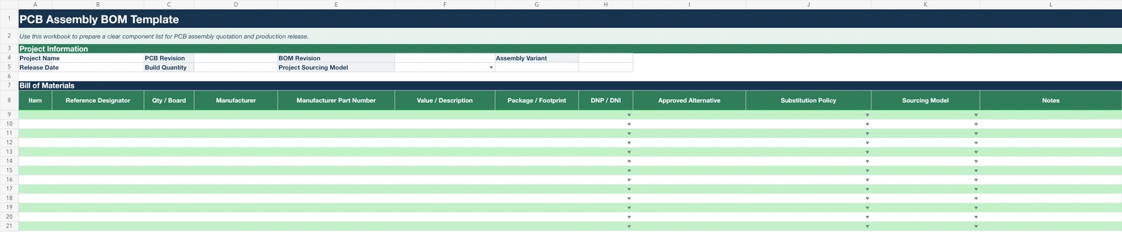
Download the PCB Assembly BOM Template
Use this editable Excel template to organize reference designators, quantities, manufacturer part numbers, DNP/DNI status, sourcing responsibility and substitution instructions before requesting a PCB assembly quotation.
Common BOM Mistakes Before PCB Assembly
- Missing Manufacturer Part Numbers. A value or generic description may not identify a unique component. “10 kΩ resistor,” for example, does not always define tolerance, voltage or power rating, package, temperature characteristics, or manufacturer variant. Some commodity passives may be controlled through an approved specification rather than one locked MPN, but that policy should be explicit.
- Incorrect or Missing Reference Designators. References should agree with the approved schematic, PCB, pick-and-place data, and applicable assembly documentation. A BOM that still lists R1–R10 after references have changed in the released design creates uncertainty about the actual fitted positions.
- Quantity Does Not Match Reference Designators. If one line lists R1, R2, R3, and R4 as fitted references, its Qty / Board should logically be 4. A mismatch can indicate an omitted reference, duplicated entry, or incorrect variant status. This check concerns per-board usage, not the final purchasing quantity.
- Confusing Qty per Board with Total Procurement Quantity. Qty / Board describes one assembly. Total purchasing demand also depends on build volume, packaging quantities, minimum order conditions, and any project-specific process allowance. Do not replace the controlled per-board quantity with a procurement total or apply a fixed attrition percentage to every project.
- Package or Footprint Mismatch. An MPN may identify a QFN while the released PCB or placement data expects another package or variant. Cross-check the MPN, package description, footprint, and assembly data for consistency. The BOM alone cannot validate every land-pattern dimension, pin assignment, or orientation detail.
- DNP / DNI Parts Are Not Clearly Marked. Assembly exclusions should not depend only on an email, verbal note, or unexplained cell color. Identify the affected references and fitted status in the controlled BOM and keep that information consistent with the assembly release.
- Alternative Component Rules Are Missing. A BOM should state whether only listed alternatives are allowed, whether the supplier may propose a candidate for approval, or whether substitution is prohibited. Purchasing should not have to infer permission from an empty cell or a generic description.
- Duplicate BOM Lines Without a Clear Reason. Separate lines for the same MPN can be legitimate when variants, sourcing responsibility, or notes differ. Unexplained duplication, however, can cause quantity and sourcing confusion. Review whether repeated lines express a real controlled difference; do not assume every identical MPN must always be merged.
- BOM Revision Does Not Match the PCB Release. A package containing PCB Rev B and an unconfirmed BOM Rev A should be clarified before quotation or production. Revision names can follow the project’s own system, but the files must describe one approved build state.
Before release, cross-check the BOM against the approved schematic, PCB data, and assembly files rather than reviewing the spreadsheet in isolation. This comparison cannot reveal every design error, but it can expose important inconsistencies in references, quantities, packages, variants, and revision identity.
How to Handle Alternative Components
An alternative component should not be treated as equivalent only because it has the same package or nominal value. Depending on the device and application, review may need to consider electrical rating, tolerance, voltage, current, power, temperature range, pinout, function, package and footprint compatibility, lifecycle, and qualification requirements. The BOM does not need to contain a complete component-engineering analysis, but it should record the resulting substitution decision and approval path clearly.
The appropriate level of control depends on project requirements. A commodity passive used well within its ratings may allow more flexibility than a timing-sensitive device, specialized connector, RF component, or qualified part. Even then, sourcing flexibility should be deliberate rather than assumed. The primary MPN, any accepted alternatives, and the policy for new proposals should be distinguishable.
Approved Alternative
An approved alternative is a substitute MPN that the customer or responsible engineering authority has already accepted for the applicable project. The BOM can place the primary MPN and approved alternative MPN in separate structured fields so purchasing can identify both without interpreting free-text notes.
Approval should still be understood in the context of the build revision and project requirements. A part approved for one product variant, operating environment, or revision is not automatically authorized for every later build. Confirm that the recorded approval applies to the release being quoted or manufactured.
Supplier May Propose Alternative
This policy allows the supplier to identify a replacement candidate when the specified part has availability, lead-time, lifecycle, or order-quantity constraints. A proposal should provide enough part information for the customer or engineering team to assess it before procurement or production use.
“May propose” does not mean “may automatically substitute.” Similar published specifications or the same package name do not remove the approval step. The accepted decision should be documented and reflected in the controlled BOM or project record.
No Substitution
No Substitution locks the specified part unless the responsible design authority changes the requirement. Depending on the project, this control may be appropriate for a critical IC, RF component, connector, safety-related part, timing-sensitive device, or customer-qualified component. These categories do not universally require a locked part; the decision depends on actual technical and qualification needs.
When substitution is prohibited, state it in a dedicated field instead of assuming that the absence of an alternative communicates the restriction. This gives quotation and purchasing teams a clear instruction if the part becomes difficult to source.
Customer-Supplied vs Supplier-Sourced Components
A PCB assembly project can use customer-supplied, supplier-sourced, or mixed sourcing. The BOM should identify responsibility at line level where necessary so quotation, purchasing, receiving, and kitting teams understand who provides each item.
Customer-Supplied / Consigned
Customer-supplied or consigned components are provided by the customer for assembly. The BOM should identify the applicable line items, expected quantity, and relevant identification or packaging information where needed. Clear records help receiving distinguish consigned material from supplier purchases and reveal shortages before assembly release without turning the BOM into a logistics or customs document.
Supplier-Sourced
For supplier-sourced items, the PCBA supplier purchases components according to the released BOM. Accurate MPNs, approved alternatives, substitution policy, quantities, and sourcing notes are especially important because they define what may be quoted and ordered. An incomplete part identity can delay quotation or require clarification before purchasing.
Mixed Sourcing
Mixed sourcing combines customer-supplied critical or restricted parts with supplier-sourced standard components. Mark responsibility for each applicable line so neither party assumes the other will purchase it. The existing BOM structure can support this directly through the Sourcing Model and Notes fields without duplicating the component list.
BOM Revision Control
The BOM belongs to a complete production release context that can include the schematic revision, PCB revision, assembly variant, Gerber or fabrication release, pick-and-place data, and assembly drawings. These files do not need to use one universal naming convention, but they should describe the same approved project state and be identifiable as a coordinated package.
Keep the BOM and PCB Release Together
For one assembly release, the BOM, PCB data, pick-and-place file, and assembly drawing should originate from the same approved state. Store or transmit them as a controlled set and identify the applicable assembly variant. This makes it easier to confirm which files belong together when a quotation is updated or a build is repeated.
Avoid Mixing Files from Different Revisions
After a PCB update, do not replace only the Gerber files while continuing to use an old BOM or placement file without checking compatibility. The reverse is also true: a revised BOM may require confirmation against the released PCB and assembly data. Not every layout change changes the component list, but any design change should trigger a check of whether the BOM, placement data, and assembly documentation also need revision.
BOM vs Pick & Place File
The BOM, pick-and-place file, and assembly drawing describe different parts of the assembly package. Their exact formats can vary with the EDA system and assembler workflow.
| File | Main Purpose | Typical Content |
|---|---|---|
| BOM | What components are required | Reference designators, quantity, manufacturer, MPN, value or description, and sourcing or substitution notes |
| Pick & Place | Where SMT components are placed | Reference designator, X/Y coordinates, rotation, board side, and placement information according to the selected workflow |
| Assembly Drawing | Visual or engineering assembly reference | Reference locations, polarity or orientation notes, and applicable mechanical or assembly instructions |
A complete turnkey PCB assembly workflow may combine component sourcing, PCB fabrication coordination, SMT assembly, and inspection using the released BOM, placement data, fabrication files, and applicable assembly documentation. The link between these files matters more than forcing every supplier to use one coordinate or rotation convention.
Need Help Preparing Your PCBA Package?
If your BOM, Gerber or placement data is still being finalized, review the files required for turnkey PCB assembly before requesting a quotation.
View Turnkey PCB Assembly Requirements
What Files Should I Send for a PCBA Quote?
Once the BOM is ready, the assembler normally needs the available fabrication and assembly data together with the required build quantity. The exact package depends on the project stage, board technology, requested scope, and supplier workflow. Not every file below is necessarily available or mandatory at the earliest quotation stage, but a clear release package supports a more accurate review.
- Gerber / PCB Fabrication Data: Provide the current approved PCB fabrication data, including the applicable board outline and drill information. Before submitting a production package, the Gerber file checklist can help you review whether the fabrication layers and drill data are complete.
- BOM: Send the controlled BOM with the applicable MPNs, reference designators, quantities, sourcing responsibility, substitution rules, fitted status, and revision identity. It should represent the same project state as the other assembly files.
- Pick & Place File: Placement data supports SMT programming and normally identifies references, coordinates, rotation, board side, and related placement information. Coordinate and rotation conventions can differ between EDA and assembler workflows, so submit the released file rather than manually reformatting it without confirmation.
- Assembly Drawing: Where applicable, include drawings that communicate component orientation, polarity, special placement instructions, and relevant assembly notes that are not clear from the BOM or placement data alone.
- Build Quantity: State the required prototype, pilot, or production quantity. Build quantity is an order requirement and should not be confused with Qty / Board, which describes component usage on one assembly.
- Special Requirements: Identify applicable soldering, inspection, testing, programming, cleaning, coating, or packaging requirements. These examples are not a universal checklist; include the requirements relevant to the requested build.
If part of the package is still being completed, send the available controlled files and identify what remains provisional. This allows the quotation team to distinguish confirmed production data from information that may change before assembly release.
Frequently Asked Questions
What information should be included in a PCB assembly BOM?
A practical PCB assembly BOM normally includes reference designators, quantity per board, manufacturer, manufacturer part number, value or description, package or footprint, and DNP or DNI status where applicable. It should also communicate sourcing responsibility, approved alternatives, substitution restrictions, notes, and revision identity when those details affect the build. The exact columns can vary according to supplier workflow and project requirements; the important point is that purchasing, engineering, and assembly teams can interpret the component identity and build variant consistently.
Is a manufacturer part number required in a PCB BOM?
A clear MPN is particularly important for most ICs, connectors, specialized components, and parts whose package or performance cannot be defined reliably by a generic description. It gives purchasing and assembly teams a specific component identity. Some commodity passives may instead be controlled through an approved manufacturer range, listed alternatives, or a sufficiently defined project specification. The BOM should make the permitted sourcing range explicit rather than implying that every line always requires exactly one locked MPN.
What does DNP or DNI mean in a PCB BOM?
DNP commonly means Do Not Populate, and DNI commonly means Do Not Install. They are generally used to identify component positions that are intentionally not fitted in a particular build variant. Terminology and internal procedures can vary between organizations, so they should not be assumed to be universally identical. What matters for production is that the released BOM and assembly information clearly identify the affected references and leave the assembler in no doubt about which positions should remain unpopulated.
Can I list alternative components in the BOM?
Yes, when project policy allows alternatives. The BOM can list an approved alternative MPN, state that the supplier may propose a candidate for engineering approval, or specify No Substitution. A matching nominal value or package does not automatically establish electrical or application equivalence. The appropriate review depends on the component and may consider ratings, tolerance, pinout, function, temperature, footprint, lifecycle, and qualification requirements before an alternative is approved.
What is the difference between a BOM and a pick-and-place file?
The BOM answers what components are required; the pick-and-place file describes where applicable components are placed. A BOM commonly contains reference designators, quantities, manufacturers, MPNs, descriptions, and sourcing or substitution notes. Placement data commonly contains references, X/Y coordinates, rotation, board side, and placement information. Their formats and coordinate conventions can vary, so both files should be generated from and checked against the same approved design state rather than treated as interchangeable.
Can a PCB assembly supplier help source components from my BOM?
Yes. Many turnkey PCB assembly workflows can include component sourcing based on the released BOM. To support an accurate review, identify primary MPNs, approved alternatives, customer-supplied or consigned parts, and any no-substitution restrictions. The BOM should also state quantities and the applicable build revision. Where a supplier is allowed to propose alternatives, the proposal and approval path should remain clear before parts are purchased or released to production.
Ready for PCB Assembly?
Send your available Gerber files, BOM, pick-and-place data, and required build quantity for quotation. If some assembly information is still being finalized, include the current release package and note any sourcing or substitution requirements.