Contents
An SMT pick-and-place file should identify each placed component by reference designator, X coordinate, Y coordinate, rotation and board side. Where available, it can also include the package or footprint, component value, description or another useful identifier. Column names, coordinate units, origin and rotation conventions can vary between EDA tools and PCB assembly workflows, so the exported data should be reviewed against the released PCB data and the receiving assembler’s requirements.
What Is a Pick and Place File?
A pick and place file is a structured set of component placement data used during preparation for SMT assembly. It tells the assembly team or its CAM system where applicable components are positioned on the PCB and provides orientation information needed to interpret that placement. The data is normally generated from the approved PCB layout rather than recreated manually.
Several names are used for this output. You may see it described as a Pick and Place file, pick-and-place file, centroid file, XY file, coordinate file or component placement file. These terms commonly refer to the same general category of SMT component placement data, but they do not guarantee an identical file structure. One EDA tool may use columns named “Designator,” “Center X” and “Center Y,” while another exporter or assembler may use different labels for equivalent information.
The exact output can also change with the EDA tool, assembler, CAM workflow and machine-preparation process. File extensions, delimiters, board-side labels and rotation values may differ even when two files describe the same PCB. For that reason, a familiar-looking spreadsheet should not be assumed to be correct solely because it contains coordinates. The data must be traceable to the approved design revision and understandable to the receiving workflow.
The basic boundary is simple: a bill of materials states what components are required, while the pick-and-place file states where the applicable components are placed. These files complement each other. Placement data does not replace sourcing information in the BOM, and a BOM does not provide the coordinates and orientation needed to prepare automated placement.
What Information Should a Pick and Place File Include?
A useful placement file makes each component location unambiguous and allows the assembler to cross-check it against the PCB, BOM and assembly documentation. The following fields are commonly included, although the required columns and their names depend on the EDA export and the assembler’s workflow.
| Field | Purpose | Important Note |
|---|---|---|
| Reference Designator | Identifies the component location, such as R1, C4 or U2 | Should match the PCB, BOM and assembly drawing |
| X Coordinate | Defines the horizontal position of the placement point | Requires a clearly defined origin and unit system |
| Y Coordinate | Defines the vertical position of the placement point | Must use the same coordinate system as the released data |
| Rotation | Describes component orientation | Interpretation depends on the export and assembler workflow |
| Board Side | Distinguishes top-side and bottom-side placements | Labels and bottom-side interpretation can vary |
| Package / Footprint | Supports package and placement-data cross-checks | Does not by itself prove that the PCB footprint is correct |
| Component Value / Description | Helps reviewers recognize the intended component | Does not replace manufacturer and MPN data in the BOM |
| Part Number / Identifier | Provides an optional library, internal or part identifier | Availability and meaning vary between workflows |
| Notes | Records a useful placement or review clarification where applicable | Special instructions should remain consistent with the approved assembly package |
Reference Designator
The reference designator is the primary link between a component record and the rest of the assembly package. Common examples include R1 for a resistor, C4 for a capacitor, U2 for an integrated circuit and J1 for a connector. Each installed location should be identifiable without relying only on a value, footprint or coordinate.
References in the placement data should correspond to the approved PCB design, BOM and assembly drawing. This consistency allows an assembler to compare the component list with the physical locations and to investigate differences before production. A coordinate may describe a valid point on the board, but it is much harder to verify when its reference does not match the design documentation.
Before release, check for missing references, duplicates and references retained from an older PCB revision. Also confirm that renumbering performed during layout has propagated to every released file. If a build variant excludes a component, its reference should be handled according to the agreed DNP or DNI workflow instead of being silently removed from one file while remaining active in another. The goal is not a particular naming pattern; it is one consistent identity for each component location across the coordinated release.
X and Y Coordinates
The X and Y fields describe the component placement point, often associated with the component centroid or another point defined by the EDA footprint and export process. Together, they locate a reference within the PCB coordinate system so that the assembly data can be prepared and checked against the board geometry.
There is no single coordinate origin that should be prescribed for every project. An origin at a board corner, a design datum or another project-defined location may be valid when it is clearly defined and used consistently. The coordinate origin should match the released PCB and assembly data, and the receiving assembler should be able to identify how the values relate to the board outline. Mixing an export based on one origin with fabrication or assembly data based on another can shift every placement even when the individual numbers look reasonable.
Units may be expressed in millimeters or inches depending on the EDA settings and downstream workflow. The important requirement is that the unit system is explicit and consistently interpreted; neither unit should be presented as universally required. Decimal precision also depends on the output and process, so a fixed number of decimal places should not be treated as a universal rule.
Review the coordinates against the actual board outline or an assembly/CAM preview. Look for unexpectedly scaled data, positions outside the intended PCB, offsets from the visible pads and inconsistencies between top and bottom data. This visual cross-check is more reliable than judging the coordinate columns in isolation.
Rotation
Rotation describes the orientation associated with each component placement. It helps the assembly workflow relate the component record to the intended pad pattern, polarity and pin orientation. However, the number in the rotation column cannot be interpreted safely without knowing how the file was generated.
The result can be influenced by the orientation of the footprint in the EDA library, the component’s placement in the PCB design, the exporter’s convention, the assembler’s CAM system, machine mapping and the board side. Two workflows may represent the same physical orientation with different numeric values. Rotation values should therefore be interpreted according to the exporting EDA tool and the receiving assembler’s workflow.
Do not infer a pin-1 direction from a rotation value alone. A value such as 0, 90, 180 or 270 only has meaning within the applicable convention, and the direction in which positive or negative values are interpreted can also depend on that convention. Library orientation is especially important: if a footprint’s reference orientation differs from what the downstream process expects, a mathematically consistent export may still require mapping during assembly preparation.
Before release, compare polarity-sensitive and asymmetric components in the PCB preview, assembly drawing and, where available, the assembler’s CAM preview. ICs, diodes, polarized capacitors, connectors and other orientation-sensitive parts deserve particular attention. Any disagreement should be resolved using the approved design and assembly information rather than by applying an assumed rotation rule to the entire file.
Board Side
The board-side field separates components placed on the top of the PCB from those placed on the bottom. Common labels include Top and Bottom, but an export may instead use T and B, TopLayer and BottomLayer, numeric layer identifiers or another documented convention. The label itself matters less than whether its meaning is clear and consistent throughout the release.
Bottom-side interpretation is one of the areas most likely to vary between workflows. The EDA view, exported coordinate data and assembly system may use different viewing directions or handle mirroring and rotation conversion at different stages. As a result, bottom-side component data should not be judged only by comparing its rotation numbers with corresponding top-side values.
Verify that each component is assigned to the intended side and compare bottom-side orientation with the assembly drawing, PCB preview and CAM preview where applicable. Pay particular attention to connectors, polarized parts and components whose physical orientation is not obvious from a symmetric package outline. If the receiving assembler specifies a particular side or viewing convention, use that documented workflow for the release rather than applying a general mirror or rotation formula.
Package or Footprint
A package or footprint field gives the assembler another way to cross-check the placement record. Values such as 0402, 0603, QFN or BGA can help reviewers identify the expected component size and placement behavior, detect an obviously mismatched record and relate the coordinate data to the corresponding land pattern.
This field is supporting information, not proof that the PCB footprint is correct. Package names are not always standardized across libraries, and two parts with similar package descriptions may differ in body dimensions, pin count, pitch, thermal pad or assembly requirements. Likewise, matching package text does not establish component compatibility. Footprint verification should still use the approved library data, component documentation, PCB design and assembly review process.
For the placement file, the practical goal is consistency: the package or footprint identifier should help relate the component record to the intended PCB location without conflicting with the BOM or released design.
Component Value or Description
A component value or short description can make placement data easier to review. Entries such as 10 kΩ, 100 nF, MCU or USB connector allow an engineer or assembler to recognize the general function of a record and compare it with the schematic, BOM and visible board location. This is useful when checking groups of passives or identifying an unexpected component type at a coordinate.
Value and description fields are not reliable substitutes for complete purchasing data. An IC, connector, crystal, power component or other specification-sensitive device may require a precise manufacturer and manufacturer part number. Even common passive values can have different tolerances, voltage ratings, packages or approved sourcing rules. Those requirements belong in the BOM. The placement file may repeat a value for convenience, but its primary role remains the description of component location and orientation.
Part Number or Identifier
Some EDA exports include an internal component identifier, library identifier, company part number or another part-number field. This information can help connect placement data to a controlled library or assist an automated comparison. In other workflows, the coordinate output contains no part number at all.
The presence and meaning of this field should therefore be confirmed instead of assumed. A library name or internal code may not be a manufacturer part number, and an exporter may populate the column from a project-specific property. A centroid file does not need to carry every sourcing field when those details are managed in the approved BOM.
Where explicit sourcing information is required, continue to rely on the BOM for the manufacturer, MPN, approved alternatives, DNP or DNI status, sourcing responsibility and substitution rules. The identifier in the placement file should support record matching without creating a second, conflicting source of component-selection data.
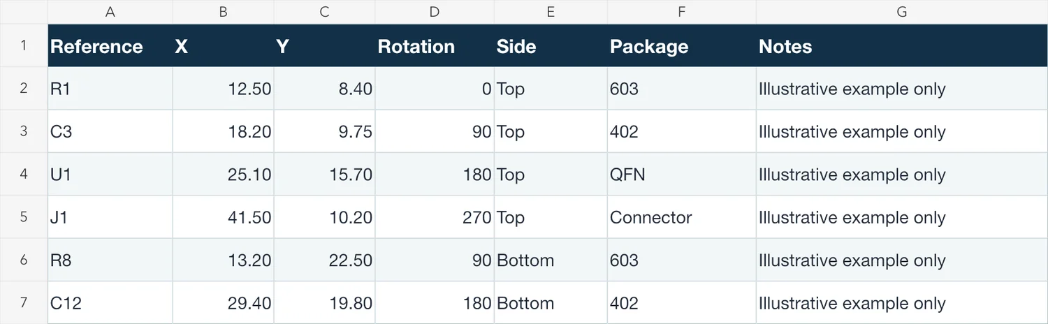
Example SMT Pick and Place File Format
Illustrative example only. The coordinate origin, units and rotation values shown below are examples and should not be treated as a universal assembly convention.
| Reference | X | Y | Rotation | Side | Package |
|---|---|---|---|---|---|
| R1 | 12.50 | 8.40 | 0 | Top | 0603 |
| C3 | 18.20 | 9.75 | 90 | Top | 0402 |
| U1 | 25.10 | 15.70 | 180 | Top | QFN |
| J1 | 41.50 | 10.20 | 270 | Top | Connector |
The example values are illustrative. Actual units should follow the agreed EDA and assembler workflow. A production export may use different column names, include additional identifiers or divide top and bottom placements into separate files. Its correctness depends on whether the data represents the approved PCB revision and is interpreted consistently—not on whether it matches this sample layout.
Download the Illustrative Pick and Place CSV
This CSV is provided only to illustrate a common placement-data structure. It is not a production-ready SMT template. Coordinates are illustrative only, and the units are not a universal recommendation. Rotation values are illustrative only, while side and bottom-side interpretation can vary between EDA tools and assembly workflows. Production placement data should normally be exported from the approved PCB/EDA project. Confirm units, origin, rotation and bottom-side interpretation with the receiving assembler.
Pick and Place File vs BOM
The BOM, pick-and-place file and assembly drawing describe different aspects of one assembly release. They should agree on component references and revision, but each file has a separate primary purpose.
| File | Main Purpose | Typical Data |
|---|---|---|
| BOM | What components are required | Reference, quantity, manufacturer, MPN, value, sourcing notes and substitution rules |
| Pick & Place | Where applicable SMT components are placed | Reference, X, Y, rotation, board side and package or footprint |
| Assembly Drawing | Visual or engineering assembly reference | Reference locations, polarity, orientation and mechanical or assembly notes |
The BOM supports material identification and sourcing. It distinguishes components that may share a value or footprint but have different manufacturers, ratings or approved alternatives. The pick-and-place file supports placement preparation by connecting each applicable reference to a coordinate, orientation and board side. The assembly drawing adds a visual engineering reference for polarity, orientation, hardware and special assembly notes that may not be clear from a spreadsheet.
These files should be released as a coordinated set. Matching references allow the assembler to connect material requirements with physical locations, while consistent revision control reduces the risk of using current Gerber data with an older BOM or placement export. DNP and DNI handling should also be clear across the files according to the agreed assembly workflow.
If the component list itself is still being prepared, see our PCB assembly BOM guide for manufacturer part numbers, DNP/DNI status, sourcing responsibility and substitution rules.
A placement file should not be treated as a substitute for that component definition, and a BOM cannot replace the position and orientation data. The assembly drawing does not replace either structured data file; it helps reviewers interpret the intended build and resolve visual or mechanical details. Together, the three documents provide a clearer basis for assembly preparation than any one of them alone.
Centroid File, XY File and Pick & Place File — Are They the Same?
Centroid file, XY file, coordinate file and pick-and-place file are often used to describe the same or closely related component placement data in a PCB assembly workflow. However, the names should not be assumed to have exactly the same meaning at every company, in every EDA tool or for every assembler. The fields inside the file are more important than its label.
Pick and Place File
Pick and place file is usually the broadest and easiest term to understand. It commonly refers to an export that connects each applicable component reference to placement coordinates, rotation and board side. Package, value or another identifier may also be included. The phrase describes the file’s role in assembly preparation without defining one required column structure.
Centroid File
Centroid file commonly emphasizes the component center or another placement point used by the design and assembly workflow. That point should not automatically be interpreted as the physical geometric center of every package. Its definition may come from the EDA footprint, library origin, exporter or downstream preparation process. Field names and included data can therefore differ between centroid outputs.
XY File or Coordinate File
XY file and coordinate file emphasize the X/Y placement values, but the file may also contain references, rotation, side, package information and other identifiers. A filename alone does not show whether units, origin, bottom-side interpretation or revision are documented clearly. The safest approach is to confirm what the receiving assembler expects rather than relying only on the file name.
Common Pick and Place File Formats
“Format” can refer to both the file container and the way its fields are organized. Common outputs include CSV, TXT, tab-delimited or comma-delimited text, spreadsheet-based exports and coordinate files generated directly by an EDA system. No single extension establishes that the data is complete or correctly interpreted.
CSV and Delimited Text
CSV and TXT files are common because engineers can inspect them and many CAM or data-preparation systems can import delimited records. A text file may use commas, tabs, semicolons or another documented separator. CSV should not be described as universally preferred: the accepted delimiter, header names and encoding depend on the receiving workflow.
Spreadsheet-Based Output
An XLSX or other spreadsheet can support human review, controlled communication and annotation. It may be useful when an assembler provides an agreed structure or when placement data needs to be reviewed alongside notes. Even then, production coordinates are best derived from the approved EDA project export rather than manually reconstructed by copying values into a spreadsheet. Manual transcription can introduce stale positions, formatting changes and revision mismatches.
EDA-Generated Coordinate Files
Generating placement data from the final approved PCB design normally gives the clearest connection to the released component locations. It reduces manual transcription and makes regeneration after a layout change more repeatable. An EDA export does not automatically guarantee correct assembly data, however. Library origins, export settings, variants, rotation handling and the selected board revision still need review.
The extension is less important than whether the release clearly communicates reference designators, coordinate units, coordinate origin, rotation convention, board side and revision identity. A receiving assembler must be able to interpret those elements without guessing.
How to Check a Pick and Place File Before PCB Assembly
Review placement data as part of the complete assembly release, not as an isolated spreadsheet. The following checks address the most common points where otherwise valid-looking data can become ambiguous.
- Confirm the file matches the released PCB revision. Generate or identify the placement output from the current approved PCB state. Do not combine a new fabrication release with an older centroid file without confirming compatibility. Record the revision so the assembler can relate the placement data to the Gerber, BOM and assembly documentation.
- Cross-check reference designators against the BOM. Compare the reference set and investigate missing, unexpected or duplicate entries. Confirm how build variants and DNP or DNI references are represented. The goal is agreement between the component list and the intended placed locations, not simply matching total row counts.
- Verify coordinate units. Identify whether the values use millimeters, inches or another explicitly agreed representation. Either common unit system can be valid when it is communicated and interpreted consistently. Watch for a file that opens at the wrong scale because its unit was assumed rather than confirmed.
- Verify the coordinate origin. Confirm how X and Y relate to the released PCB, board outline and assembly/CAM workflow. The origin may be project-defined; it does not need to follow one universal location. Overlaying or previewing the data can reveal a uniform offset caused by inconsistent origins.
- Check that components fall within the intended board area. Use a PCB viewer, assembly tool or CAM preview to look for shifted, scaled or outlying placements. For a panelized project, clarify whether the coordinates describe a single board or the panel so that valid single-board data is not mistaken for panel-level placement, or vice versa.
- Review top and bottom side assignments. Confirm that each reference is assigned to the intended side. Bottom-side review should include orientation and viewing interpretation, not only the side label, because transformations can occur at different stages of the export and assembly workflow.
- Review rotation against a visual reference. Compare the data with the PCB layout, assembly drawing or CAM preview, paying particular attention to ICs, connectors, diodes, LEDs, electrolytic capacitors and other polarized or asymmetric components. Do not apply a presumed rotation mapping to every record.
- Confirm DNP and DNI handling. If excluded components appear in the placement file, clarify how the assembler will process them. One workflow may retain a flagged reference, another may exclude it, and another may manage the instruction through the BOM or assembly notes. The released files should communicate one consistent build intent.
Do not review the placement file as a text table alone. Where possible, compare it with the PCB layout, assembly drawing or CAM/placement preview. A preview is an important cross-check, although it does not by itself prove that every library definition or assembly instruction is correct. This review also shows how the placement data enters an in-house SMT assembly workflow without turning the data-preparation task into a capability specification.
Preparing the Full PCBA Package?
A placement file works together with the BOM, Gerber data and assembly documentation. Before quotation, confirm that the released files refer to the same PCB revision and clearly identify component sourcing and placement requirements. Review the PCB Assembly BOM Guide as an educational next step when checking the component-list portion of the package.
Common Pick and Place File Mistakes
Most placement-data problems come from inconsistent releases or undocumented interpretation rather than an unusual file extension. Check for these issues before sending the assembly package:
- Missing or duplicate reference designators. A missing reference can leave an intended component without a placement record, while a duplicate makes it unclear which coordinates apply. Compare references with the approved PCB and BOM.
- X/Y units are unclear or incorrectly interpreted. Correct numeric values can produce a scaled placement when the sender and receiver interpret units differently. State or confirm the unit system instead of relying on the magnitude of the numbers.
- The coordinate origin is wrong or unexplained. A consistent offset across many components may indicate that the placement and PCB data use different origins. Document the project datum and verify alignment visually.
- The rotation convention is mismatched. A visually correct orientation in the EDA editor can still be interpreted differently downstream when footprint zero orientation, exporter behavior and machine mapping are not aligned. Resolve the convention with visual assembly data rather than assigning an industry-wide meaning to specific angle values.
- Bottom-side mirroring or orientation is misinterpreted. Bottom-side data may require transformation depending on the EDA export, viewer perspective and assembler CAM workflow. Cross-check it against the PCB and assembly view instead of applying a fixed mirror rule.
- The placement data comes from an older PCB revision. A board outline or component move may change the coordinates without changing every BOM line. Regenerate and review the coordinated release after layout changes.
- DNP or DNI parts remain without clarification. Their presence is not automatically an error, but the assembler needs to know whether they are flagged, excluded or controlled through another approved document.
- Reference designators do not match the BOM. Renumbering, variant changes or mixed revisions can break the link between sourced parts and physical locations even when both files appear complete.
- Coordinates fall outside the intended board or panel context. Outlying positions may indicate the wrong origin, scale, board instance or panel interpretation. Confirm whether the data represents one PCB or a manufacturing panel.
- Package or value information conflicts with released data. A package or value mismatch can reveal an outdated export or library inconsistency. Resolve it against the approved PCB library and BOM rather than editing one file in isolation.
A pick-and-place file should not be treated as a replacement for the BOM, fabrication data or assembly documentation. Those files describe different parts of the same controlled release.
How Do Altium, KiCad and Other EDA Tools Export Placement Data?
Major PCB design tools can generate component position or placement outputs from the PCB design environment. The menu name, file extension, column labels and options may change with the software version, project configuration and selected output workflow, so a software-independent checklist remains useful.
Altium Designer
Altium Designer can generate component placement or pick-and-place manufacturing output from a PCB project. Available settings and interface paths may vary by version and configuration. For this guide, the important point is to export from the approved PCB state and then verify references, units, origin, rotation, side and revision. A version-specific Altium export procedure is a separate tutorial intent.
KiCad
KiCad can generate component position or placement files from its PCB design environment. The resulting data should be reviewed for the applicable fields, coordinate interpretation, side assignments and bottom-side orientation before release. Exact steps and interface labels should be documented for the relevant KiCad version in a dedicated software tutorial.
Other EDA Tools
Cadence, Siemens/Mentor and other PCB CAD systems also provide ways to produce assembly or component-coordinate data. Their terminology and output structure can differ. Regardless of the EDA tool, confirm that the export came from the correct design revision and verify it against the visual PCB and receiving assembler’s workflow before release.
What Files Should I Send for SMT Assembly?
A practical SMT assembly release normally combines fabrication, component and placement information. The exact package depends on the project and assembler, but the following items provide a useful starting point:
- PCB fabrication data: Gerber or other accepted fabrication data from the approved revision. Use the Gerber file checklist when reviewing the fabrication portion of the release package.
- BOM: Component identity, quantity, manufacturer/MPN and agreed sourcing or substitution information.
- Pick and place file: Component references, placement coordinates, orientation and board-side data according to the agreed workflow.
- Assembly drawing: Where applicable, a visual reference for component locations, polarity, orientation and special assembly notes.
- Build quantity: The required prototype, pilot or production quantity so material and process planning reflect the intended build.
- Special assembly requirements: Relevant soldering, inspection, testing, packaging or customer-supplied component instructions.
Keep these files under consistent revision control and identify any exceptions before quotation or production preparation. For projects that combine component sourcing, SMT assembly and inspection, review the turnkey PCB assembly workflow and its required project files.
Frequently Asked Questions
What is a pick and place file in PCB assembly?
A pick-and-place file contains component placement information used to prepare SMT assembly. It commonly identifies each applicable component by reference designator, X coordinate, Y coordinate, rotation and board side. Some workflows also include a package or footprint, value, description or another component identifier. The file describes where components are positioned and how their orientation is represented; it does not replace the BOM, which defines the required parts and sourcing information.
What columns should a pick and place file include?
Common columns include Reference, X, Y, Rotation and Side. Package or Footprint, Value, Description and a part or library identifier may also be useful when available. These names are not a mandatory column standard: an EDA exporter or assembly workflow may use different labels for equivalent data, and the receiving assembler may require additional fields. The column meanings, units, origin and revision should be clear enough to interpret without guesswork.
Is a centroid file the same as a pick and place file?
The terms are often used for the same general type of component placement data, but they are not guaranteed to describe an identical field structure. Centroid file, XY file, coordinate file and pick-and-place file frequently overlap in practical assembly workflows. One output may emphasize component center coordinates, while another includes additional reference, rotation, side or package fields. Judge the file by its documented data and the receiving assembler’s requirements rather than by its filename alone.
What coordinate origin should I use for a pick and place file?
There is no single coordinate origin that applies to every PCB assembly workflow. The origin should be clearly defined, consistent with the released PCB and assembly data, and understood by the receiving assembler. A project-defined board datum, design origin or another agreed reference can work when all related data aligns. Where possible, load or overlay the exported placement data in a PCB, assembly or CAM preview to check its scale and position against the intended board outline.
How should component rotation be specified?
Component rotation should be specified according to the convention used by the exporting EDA tool and the receiving assembler’s workflow. Its interpretation can depend on footprint reference orientation, exporter behavior, CAM preparation and top- or bottom-side handling. A numeric angle should not be assigned a universal pin-1 direction or rotation sense. Verify orientation-sensitive parts against the PCB preview, assembly drawing or CAM view, and resolve any disagreement before releasing the assembly package.
Can a PCB assembly supplier use CSV or TXT pick and place files?
Often yes, provided the receiving assembler can clearly interpret the file structure and placement data. CSV, TXT and other delimited files are common, but acceptance depends on the specific CAM and assembly workflow. The important details are the reference fields, coordinate units, coordinate origin, rotation convention, board side and revision—not the extension alone. Confirm the expected delimiter, headers and any additional identifiers with the supplier rather than assuming CSV is preferred in every case.
Ready for SMT Assembly?
For an SMT assembly quotation, provide the available Gerber package, approved BOM, placement data and intended build quantity. When coordinate or rotation details remain unresolved, attach the current assembly release and identify the points that need review, including any known sourcing requirements.