Contents
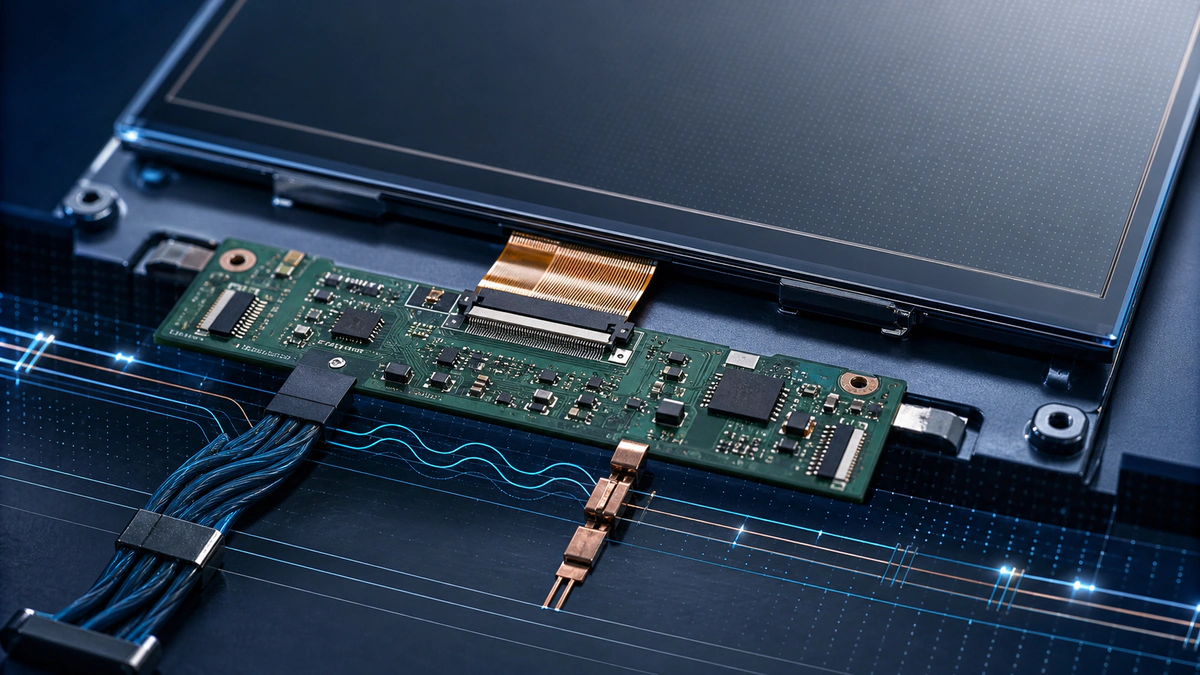
LCD and touchscreen PCB design must coordinate the display interface, touch controller, backlight power, grounding, ESD protection, mechanical connector, and noise-sensitive routing. The correct architecture depends on the display module, interface speed, cable or connector, panel size, touch technology, enclosure, and product environment.
Start with the Display Module Specification
Confirm supply rails, interface type, resolution, pixel clock, timing, connector pinout, cable length, logic levels, reset and enable sequencing, backlight requirements, and mechanical drawing. Do not copy routing rules from another module without checking the selected display and processor documentation. Where the display module mates through another PCB, coordinate board-to-board connector design with the pinout, stack height, and mechanical drawing.
Display Interface Routing
RGB, LVDS, MIPI DSI, eDP, SPI, and parallel interfaces have different bandwidth, topology, impedance, skew, and reference-plane needs. Maintain return-path continuity, minimize stubs, control pair spacing, and coordinate connector launches with the stackup.
Backlight Power Design
The backlight driver must support LED voltage, current regulation, dimming method, startup behavior, efficiency, thermal dissipation, and fault protection. Keep high-di/dt switching loops compact and separated from touch sensing and sensitive analog sections.
Capacitive Touch Noise Control
Capacitive touch controllers measure small signal changes and can be disturbed by display clocks, backlight switching, chargers, DC/DC converters, cables, and ground noise. Follow the controller vendor’s layout guidance for sensor routing, shielding, ground references, filters, and component placement.
ESD and Connector Protection
Place ESD protection close to the external connector and route the discharge path to the intended chassis or ground structure with low inductance. Protection-device capacitance must be compatible with high-speed signal channels.
Mechanical and Assembly Checks
Verify connector orientation, flex-cable insertion, stiffener clearance, board thickness, mating cycles, display mounting, bezel pressure, component heights, and service access. Confirm polarity and pin-one marking in assembly documentation.
Release Checklist
Review interface constraints, power sequencing, backlight thermal behavior, touch noise, ESD paths, connector footprint, mechanical fit, and production test access. Excel Circuit supports PCB design and layout engineering.