Contents
A PCB short circuit is an unintended low-resistance connection between conductors that should remain electrically separate. Shorts can originate in the design database, bare-board fabrication, solder-paste printing, component placement, reflow, contamination, damage, or rework, so prevention must cover the complete design-to-assembly process.
Design Causes of PCB Shorts
Incorrect net connectivity, footprint errors, inadequate spacing, copper slivers, poorly defined plane clearances, via-to-pad conflicts, exposed copper, and unreviewed library changes can create direct or latent shorts. PCB library and design reuse controls, including ERC, DRC, netlist comparison, and controlled library release, reduce these risks.
Fabrication Risks
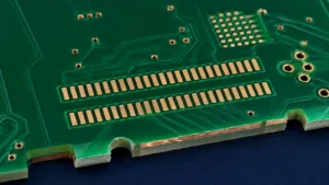
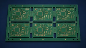
Imaging defects, under-etching, conductive residues, drill or plating anomalies, mask registration, and handling damage can bridge conductors. Bare-board electrical test verifies connectivity against the supplied netlist, while visual and automated inspection help identify physical defects.
SMT Assembly Risks
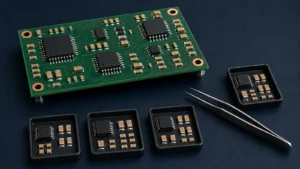
Excess solder paste, aperture design, placement offset, component coplanarity, solder-ball formation, tombstoning, disturbed paste, and an unsuitable reflow profile can create bridges. Fine-pitch ICs and BGAs require process capability matched to pad geometry and inspection access.
How to Inspect a Suspected Short
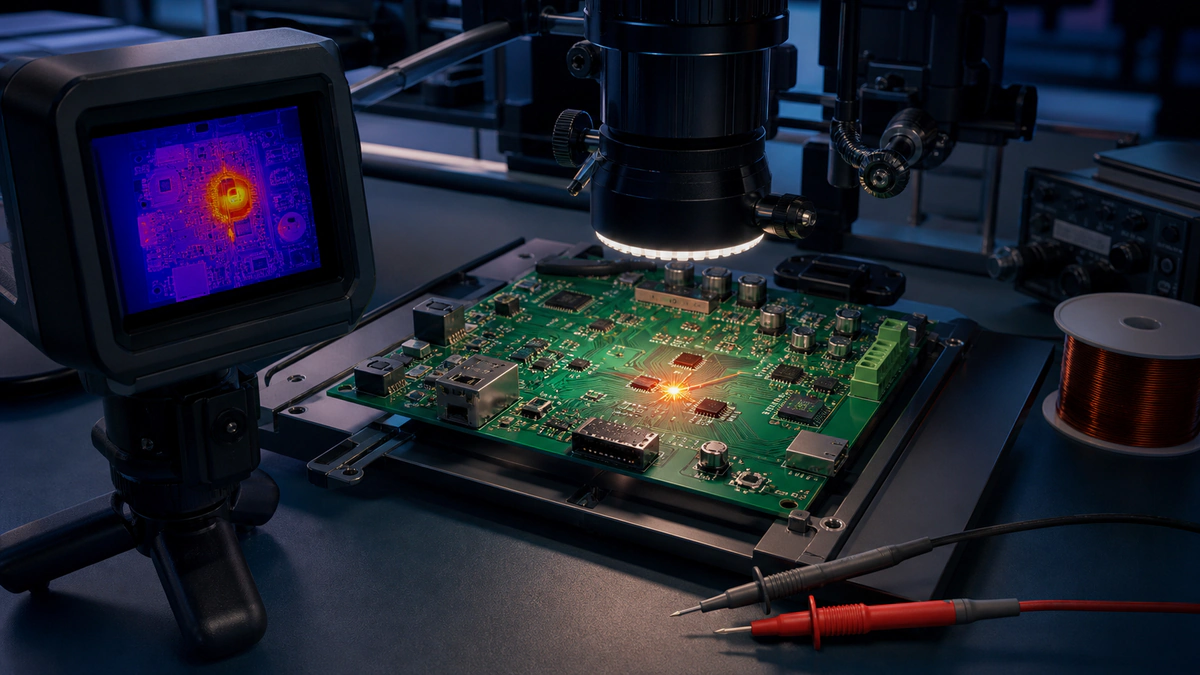
Power must be removed before resistance or continuity measurements. Compare resistance between the affected nets, isolate sections where practical, inspect under magnification, use X-ray for hidden joints, and apply current-limited diagnostic methods only under an approved troubleshooting procedure. Avoid uncontrolled high current that can damage traces or components.
Prevention Checklist
Verify schematic and footprints; run final DRC and netlist checks; inspect Gerber and drill outputs; confirm mask and stencil data; control paste printing and placement; use AOI or X-ray where appropriate; perform bare-board electrical test and assembly electrical test; document all rework.
Design-to-Assembly Support
Use the PCB DFM guide before release and coordinate inspection through PCB testing services.