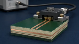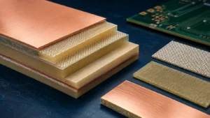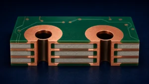
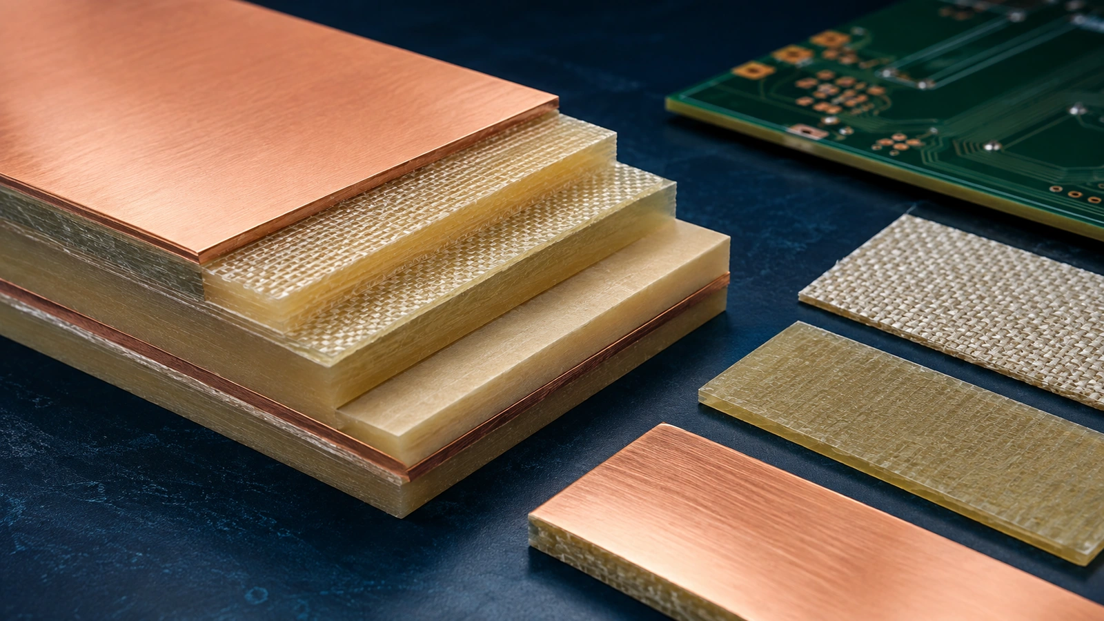
FR-4 describes a broad class of PCB materials, not one fixed electrical or thermal performance level. PCB material selection should consider Tg, Td, CTE, Dk and Df alongside operating temperature, reflow exposure, layer count, via structure, signal speed, frequency, loss budget and mechanical requirements.
A high Tg number alone does not establish the right laminate. Compare the properties that constrain the actual product, using their test methods and conditions, then confirm the available core and prepreg construction with the fabricator. Material choice must support both fabrication and the assembled board’s intended service.
| Property | What it represents | Why it matters | Do not assume |
|---|---|---|---|
| Tg | Glass-transition behavior | Changes in mechanical response with heat | That it is the maximum operating temperature |
| Td | Decomposition under a defined test | Thermal degradation resistance | That it is a safe service-temperature rating |
| CTE | Expansion with temperature | Dimensional and plated-hole reliability | That all directions and temperature ranges are identical |
| Dk | Relative dielectric permittivity | Impedance and propagation | One value applies to every construction or frequency |
| Df | Dielectric dissipation | Contributes to signal attenuation | That it accounts for all channel loss |
| Moisture absorption | Water uptake under defined conditions | Electrical and reliability behavior | A dry datasheet value describes every environment |
What does FR-4 mean?
FR-4 is a flame-retardant glass-reinforced epoxy laminate category commonly used for rigid PCBs. Different resin systems, glass constructions and grades can meet the category while offering different thermal and electrical properties.
A drawing that says only FR-4 may leave important choices open. For an uncomplicated board, an agreed general material specification may be sufficient. For a demanding thermal or electrical application, identify the required properties or approved material system and confirm the actual construction.
Do not confuse laminate selection with surface finish. The laminate forms the dielectric and mechanical structure; the finish serves exposed copper surfaces. Selecting one does not establish the suitability of the other.
Glass transition temperature: Tg
Tg describes the transition of the resin system from a relatively rigid glassy state toward a more compliant state as temperature rises. Mechanical properties and thermal expansion behavior change through this transition; Tg does not describe melting of the complete glass-reinforced laminate.
Tg is not a maximum operating temperature. Long-term service depends on the material system, exposure duration, loading, electrical requirements and applicable qualification. A design should not choose its permitted operating temperature simply by staying below a datasheet Tg.
Repeated thermal exposure makes the surrounding properties important. Compare the relevant expansion and thermal-reliability data, and identify the method used to measure Tg. Values obtained by different techniques may not be directly interchangeable.
The purchasing decision should preserve the qualified material behavior, not just a minimum Tg label. If the assembler expects multiple soldering or rework exposures, communicate that process history before approving a laminate.
Decomposition temperature: Td
Td describes chemical degradation under a specified thermal test, commonly using a defined mass-loss criterion. It is a different phenomenon from the glass transition and should be interpreted with its test method and criterion.
Crossing Tg changes physical behavior; decomposition involves degradation of the material chemistry. Neither number alone defines a safe continuous operating temperature. A high Td does not establish that the board can tolerate indefinite exposure near that value or repeated assembly cycles without other damage.
Ask for the material manufacturer’s relevant thermal data and fabrication guidance. Compare like-for-like test conditions and review the intended assembly profile, rather than selecting a material by the largest temperature number on a datasheet.
Coefficient of thermal expansion: CTE
CTE describes dimensional change with temperature. A reinforced PCB laminate can behave differently in its x, y and z directions, and its expansion behavior can change across the glass transition.
Z-axis expansion is particularly relevant to plated through holes because the dielectric and copper barrel respond differently during thermal exposure. Board thickness and construction influence the strain relationship. The result cannot be predicted from Tg alone.
For thermal cycling, compare the relevant directional expansion data and temperature range with the product’s expected exposure. Ask what reliability evidence supports the proposed construction, especially for thick multilayer boards or demanding service conditions. Do not use an unsupported universal CTE threshold as a guarantee against barrel damage.
In-plane expansion also matters for mechanical and dimensional compatibility. Keep detailed warpage prediction and mechanical constraint analysis with their dedicated reviews.
Dk: dielectric constant
Dk is relative dielectric permittivity: it describes how the dielectric responds to an electric field compared with vacuum. In a PCB transmission-line structure, it influences capacitance, impedance and propagation behavior together with the geometry.
Datasheet Dk is not one immutable value. Frequency, test method, material direction, resin content and glass construction can influence the reported or effective value. A design value derived for circuit modeling may differ from a value measured for material quality control.
Use a Dk basis appropriate to the intended frequency range and construction, and confirm it with the supplier. If a model and datasheet use different methods, document the difference instead of treating it as an automatic contradiction. Preserve the modeling assumptions when approving alternative materials.
Df: dissipation factor
Df, also called loss tangent, describes dielectric dissipation. It contributes to signal attenuation and becomes important when the frequency range, route length and channel loss budget make dielectric loss significant.
Total insertion loss also includes conductor-related effects and other parts of the channel. Copper roughness, conductor geometry, transitions and connectors can matter. A low-Df laminate therefore does not by itself establish a passing channel.
Compare Df at relevant frequencies and compatible test conditions. Ask whether the proposed material and copper construction fit the design’s loss budget. Avoid ranking materials using a single headline value when the values were measured by different methods or under different conditions.
Tg versus Td: different thermal questions
Tg and Td describe different material responses, so one cannot substitute for the other. Higher Tg does not automatically mean lower dielectric loss or better signal performance.
| Question | Tg | Td |
|---|---|---|
| What changes? | Physical transition in resin behavior | Chemical degradation under the test |
| What should be compared? | Method and transition criterion | Method and decomposition criterion |
| What does it not establish? | Maximum service temperature or low loss | Safe operating temperature or unlimited reflow exposure |
A useful material review considers these properties alongside CTE, the complete construction and relevant thermal-reliability evidence. It should state the actual exposure the board must survive, rather than replacing that requirement with a single material label.
Dk and Df for high-speed digital applications
High-speed digital material selection connects controlled impedance with channel loss and timing requirements. The relevant frequency content depends on signal behavior, including edge rates; the nominal clock frequency alone is not a complete material-selection criterion.
Use the DDR routing and signal-integrity guide for design-side topology and timing. Material selection should supply appropriate electrical properties and construction consistency for that design, not replace the routing review.
A premium laminate is not automatically required for every high-speed interface. Evaluate the actual route length and loss budget, then confirm a suitable construction. Changes between material grades can require revised geometry or analysis even when both are marketed for high-speed use.
Dk and Df for RF applications
RF circuits can be sensitive to dielectric consistency, frequency-dependent behavior, loss and controlled thickness. The needed performance depends on the circuit function and operating band, rather than an unrestricted rule that all RF requires one material family.
Compare relevant material data and confirm the dielectric thicknesses available for the proposed construction. Include temperature or environmental stability when the application requires it. The RF PCB design guide owns layout and signal-integrity decisions; this review establishes the material assumptions supporting them.
Avoid treating a brand name as a complete specification. Identify the approved grade and construction, or the measurable requirements an alternative must meet, without turning a property review into a laminate catalog.
Material selection and PCB stackup
A multilayer stackup combines cores, prepregs and copper into the finished structure. Available thicknesses, resin content, glass reinforcement and lamination behavior influence the result. Two constructions using the same material family need not have identical dielectric spacing or electrical behavior.
Coordinate the material system with the PCB stackup design guide. Ask the fabricator to confirm the proposed core and prepreg combination, finished thickness and copper assumptions before the design is released.
Distinguish fixed customer requirements from supplier-selected details. If a particular dielectric spacing or mechanical thickness is critical, document it alongside material approval. A material datasheet alone does not establish the finished board stackup.
Material selection and via reliability
Material expansion and thermal behavior interact with plated barrels and multilayer thickness during fabrication, assembly and service. CTE is therefore relevant to interconnect reliability, but it is only one part of the construction.
Hole geometry, plating, process quality and thermal exposure also need review. The PCB via types guide explains interconnect options; material selection should confirm that the chosen system supports the intended via structure and reliability requirements.
Do not infer a universal lifetime from Tg or a nominal CTE value. For critical products, identify the relevant qualification evidence and acceptance conditions. Detailed via-failure mechanisms and accelerated testing remain separate engineering topics.
Material selection and reflow
Assembly exposes the board to a time-and-temperature history, potentially including multiple reflow, secondary soldering and rework operations. Lead-free assembly considerations can make thermal robustness important, but the actual process must be evaluated.
Provide the intended thermal exposures and ask the fabricator and assembler to confirm material compatibility. Tg and Td should be considered with the construction, moisture condition and relevant thermal-reliability data. Do not assign a universal permitted number of reflow cycles to unnamed FR-4.
Where storage or moisture handling is important, follow material and assembly guidance. A short discussion of those requirements supports material selection; it does not replace a dedicated moisture-control or cleaning procedure.
Material substitution
An equivalent material substitution requires review of the properties and approvals that matter to the product. Matching Tg alone is insufficient if the replacement changes electrical properties, expansion, available thicknesses or the qualified resin system.
Compare Dk and Df using compatible conditions, directional CTE, thermal characteristics, core and prepreg availability, copper compatibility and relevant UL or customer specifications. Determine whether the substitution changes the approved stackup or requires additional qualification.
Record who may approve the replacement and how it is identified in the production documentation. For controlled lines, review the controlled-impedance manufacturing and reporting requirements. A coupon pass verifies the agreed impedance condition; it does not independently prove equivalent loss, thermal reliability or certification status.
When standard FR-4 may not be enough
A conventional FR-4 construction may be unsuitable when the product requires very low channel loss, demanding RF consistency, elevated-temperature performance or severe thermal-cycling reliability. High layer count and complex interconnects can also increase the importance of material and construction qualification.
Start with the unmet requirement, then compare suitable alternatives. Do not assume a premium material is necessary merely because a design is multilayer or uses a fast interface. The decision should identify the limiting property and the evidence that a proposed alternative addresses it.
Include availability, fabrication compatibility and cost in that comparison after the functional requirements are clear. No generic percentage premium or lead-time promise is necessary to make a defensible selection.
PCB material selection checklist
- Application: identify product function and required reliability.
- Frequency and data rate: establish the relevant electrical operating conditions.
- Loss budget: distinguish dielectric loss from the complete channel.
- Operating temperature: define service exposure independently of Tg or Td.
- Reflow: communicate assembly and anticipated rework history.
- Layer count: confirm the proposed multilayer construction.
- Via structure: review interconnect compatibility and qualification needs.
- Impedance: use an appropriate Dk basis and controlled stackup.
- Mechanics: confirm thickness, expansion and interface requirements.
- Certification: identify applicable customer, UL or other specified approvals.
- Supply: confirm availability and a controlled substitution process.
Information required from the customer
Provide the proposed stackup, target thickness, layer count, operating environment and mechanical or thermal requirements. Include impedance targets, high-speed or RF performance needs, loss constraints and assembly exposure. Identify preferred or approved laminate grades and applicable customer specifications.
If the material is not fixed, describe the requirements it must meet and who approves the final proposal. Request a construction-specific response rather than a list of headline datasheet values. Retain the approved material and stackup revision with the release package.
Review the material system before fabrication
Excel Circuit offers in-house PCB design engineering, qualified PCB manufacturing resources, component sourcing and in-house SMT assembly. Its PCB manufacturing coordination services help connect material requirements with the proposed fabrication and assembly route.
Send your stackup, operating requirements and impedance targets if you need the PCB material system reviewed before fabrication. Submit your PCB material review inputs.